Choices: Two's Complement, Offset Binary
Default: Two's Complement
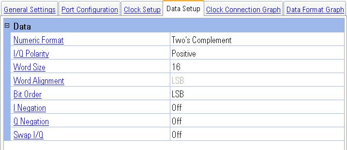
Selects the binary format used to represent the transmitted data values.
|
Two's Complement |
This choice selects the N5102A module data format to a two’s complement
representation of the data values. |
|
Offset Binary |
This choice selects the N5102A module data format to an offset binary
representation of the data values. |
This selection may be changed even while the waveform is playing.
Choices: Positive, Negative
Default: Positive
Selects the logic level for I and Q data.
|
Positive |
This choice selects a high logic level at the output as a digital one. |
|
Negative |
This choice selects a low logic level at the output as a digital one. |
This selection may be changed even while the waveform is playing.
Range: 4 to 16
Default: 16
Resolution: 1
Sets the number of bits in each sample transmitted through the N5102A module. A word is defined as an integer number of bits from 4 to 16. For parallel and parallel interleaved data, word is synonymous with sample. Any unused data lines are driven low. The word size is coupled with Word Alignment. When this value is changed, the Data Format Graph is updated to reflect the changed value. Refer to Digital Lines, Digital Signals, and Data Format for examples of this change.
Choices:
Default:
Dependency: Displayed only when Port Configuration is set to Parallel and
available only when Word Size is set to less than 16
Selects the bit alignment of words smaller than 16 bits to begin at either boundary of the data bus. The word alignment is coupled with the word size and the word order. This command is only valid in parallel mode. When this value is changed, the Data Format Graph is updated to reflect the changed value. Refer to Data Format for examples of this change.
|
|
With this choice, the data will be aligned with the left data boundary (data line zero) for both I and Q. |
|
|
With this choice, the data will be aligned with the right data boundary (data line 15) for both I and Q. |
Choices:
Default:
Selects the bit order for data transmitted through the N5102A module. In serial mode, data can be in least significant (LSB) bit first or most significant (MSB) bit first (data line zero). In parallel mode, you can assign the bit order of the data words to either the lowest or highest lines of the data word. When this value is changed, the Data Format Graph is updated to reflect the changed value. Refer to Digital Signals and Data Format for examples of this change.
|
LSB |
With this choice, for a serial port configuration, the LSB of the data will be the first bit (data line zero) in a sample. In parallel or parallel interleaved port configuration, the LSB of the data word will appear on the lowest lines of the data word. |
|
MSB |
For a serial port configuration, the MSB will be the first bit in a sample. In parallel or parallel interleaved port configuration, the MSB of the data word will appear on the lowest lines of the data word. |
Choices: ON, OFF
Default: OFF
Enables or disables negation of the value of each sample of the I data. Negation changes the affected sample by expressing it in two's complement form, multiplying by negative one, and converting back to the selected numeric format. Negation can be done for I samples, Q samples, or both.
|
On |
With this choice, the I data is negated. |
|
Off |
With this choice, no negation is performed. |
This selection may be changed even while the waveform is playing.
Choices: ON, OFF
Default: OFF
Enables or disables negation of the value of each sample of the Q data. Negation changes the affected sample by expressing it in two's complement form, multiplying by negative one, and converting back to the selected numeric format. Negation can be done for I samples, Q samples, or both.
|
On |
With this choice, the Q data is negated. |
|
Off |
With this choice, no negation is performed. |
This selection may be changed even while the waveform is playing.
Choices: ON, OFF
Default: OFF
Enables or disables swapping of the I and Q data. When enabled, the ’I’ data is sent to the Q bus and the ’Q’ data is sent to the I bus on the N5102A module. When this value is changed, the Data Format Graph is updated to reflect the changed value. Refer to Digital Signals for examples of this change.
|
On |
With this choice, the I data is available on the Q data bus and the Q data is available on the I data bus. |
|
Off |
With this choice, I and Q data are not swapped. |
This selection may be changed even while the waveform is playing.
General Settings
Port Configuration
Clock Setup
Clock Connection Graph
Data Format Graph
