|
|
Not all of the parameters listed below are displayed simultaneously. For some channel models, the Fader settings for the associated parameter are displayed above the Fader Setup parameters when the channel model is selected. When multiprobe MIMO OTA channel models are selected, the Cluster Weighting tab replaces the Power Imbalance tab. |
Displayed only when LTE High Speed Train is the selected Channel Model
Displayed only when a W-CDMA BS or W-CDMA MS Birth-Death profile is the selected Channel Model.
Correlation Type and Power Azimuth Spectrum are not displayed simultaneously.
HSPA Precoding Matrix
High (Hex)
Middle (Hex)
Low (Hex)
Dependency: Displayed only when LTE High Speed Train is selected as the Channel Model
Default:
Tunnel: 150 m; Open Space: 500 m
Range: 10 m to 100 km
Sets the initial distance (Ds/2) that the mobile must travel before passing the base station (assuming that the initial distance is much larger than Dmin) when using the LTE high speed train channel model.
Default: Tunnel: 2 m; Open Space: 50 m
Range: 0 to 1 km
Sets the minimum distance from the mobile to the base station (BS-Railway track distance) when using the LTE high speed train channel model.
Default: Tunnel: 300 km/h; Open Space: 350 km/h
Range: 0 to 1000 km/h
Sets the train speed when using the LTE high speed train channel model.
Default: Tunnel: 1.15 kHz; Open Space: 1.34 kHz
Range: 0 to 1.6 kHz
Sets the maximum Doppler frequency for the channel when using the LTE high speed train channel model.
Dependency: Displayed only when a
W-CDMA BS or W-CDMA MS Birth-Death profile is the selected Channel Model.
Range: –25 to –0.1 ms
Default: –5.0 ms
Sets the minimum birth-death path delay when you select a Birth-Death delay profile for W-CDMA BS/MS. Although the minimum delay property is a negative value, the delay bins are actually shifted to the positive while maintaining the same bin spacing.
Range: 0.1 to 25 ms
Default: 5.0 ms
Sets the maximum birth-death path delay when you select a Birth-Death delay profile for W-CDMA BS/MS.
Range: 1 to 5 ms
Default: 1 ms
Sets the minimum step size of the random hops when you select a Birth-Death delay profile for W-CDMA BS/MS.
Range: 0.1 to 1 s
Default: 0.191 s
Sets the duration for each birth-death state when you select a Birth-Death delay profile for W-CDMA BS/MS.
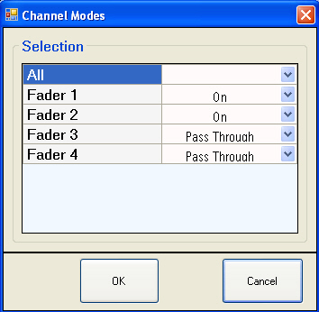
Choices: On, Pass Through, Off,
Accesses a  dialog box
where you can turn fading on, off, or allow the faded signal to pass through
a fader block. Mixed is displayed if not all faders use the same mode.
dialog box
where you can turn fading on, off, or allow the faded signal to pass through
a fader block. Mixed is displayed if not all faders use the same mode.
On
Applies fading to the signal on the selected fader block in the configuration.
Pass Through
Passes the signal through the fader block without applying fading. This allows easier synchronization between the device-under-test (DUT) and the PXB with the same fader backoff as with the fader enabled.
Off
Turns the fader off; no signal is transmitted through the selected fader block.
Choices: On, Off
Turns dynamic fading on or off. With dynamic fading on, the dynamic fading feature will be started the next time the waveform is played. (Dynamic fading is not available for the following profiles: W-CDMA Birth Death, W-CDMA Moving Propagation, or High Speed Train.)
Dynamic fading uses data that you define to dynamically change the relative path loss, path delay, and UE speed for up to 24 paths for each fading channel. The data for dynamic fading is entered from a dynamic fading scenario file.
This cell is only visible when dynamic fading is enabled.
![]() Accesses a window from which you can browse
to select a previously saved file that contains the fading scenarios to
use for dynamic fading.
Accesses a window from which you can browse
to select a previously saved file that contains the fading scenarios to
use for dynamic fading.
A Microsoft Excel spreadsheet template is provided to create the dynamic fading scenario file. The Agilent Dynamic Fading Template can be found at the following places:
On the PXB Desktop
In the C:\<Program Files for Win XP><Program Files (x86) for Win 7>\Agilent\PXB\Infrastructure\Applications\Fading directory
On the internet at http://www.agilent.com/find/PXB under the Technical Support tab
Refer to Dynamic Fading for complete instructions on how to create the dynamic fading scenario file.
Choices: See table
Selects a default or standard-based fading model. The standard models cover general propagation environments that allow you to test whether your device meets the performance requirements as defined by their respective standard. Path configurations, antenna setup, and correlation are automatically populated for the selected standard model.
After selecting a model, the firmware provides options to customize path configurations, antenna setups, or the correlation matrix. Since MIMO system performance is known to deteriorate substantially if the antenna spacing is insufficient or the scattering environment does not provide completely uncorrelated signals, these options allow you to thoroughly test your DUT or subsystem operation under a wide variety of environmental conditions.
Default: 2.4 GHz
Range: 1 to 44 GHz
Sets the carrier frequency to be used for Doppler effects in the fading simulations. The carrier frequency is coupled either to the Doppler frequency or the vehicle speed as selected under Carrier Frequency Coupling in the Fader Path Setup view.
Each fading channel has its own carrier frequency setting. It is set to couple to the external input device by default, although coupling is user-selectable in the System > Get Carrier Frequency From menu. See the Menu Bar topic for more information.
Dependency: Only active when using
standard path configurations and correlation source
Choices: Low, Medium, High,
Selects the correlation that best typifies the antenna relationships between the base station and mobile station when using a standard channel model.
For Mobile WiMAX, the predefined correlation types are defined in the WiMAX Forum Mobile RCT-Wave 2 Amendment. ®
For LTE, the predefined spatial correlation matrixes are defined in 3GPP TS 36.101 V8.3.0 (2008-09), Annex B.2.3.
|
|
Mobile WiMAX |
LTE |
|
Low |
Selects a spatial and polarization correlation (BS 4λ, MS λ/2 cross-polarized) in a 2x2 configuration. |
Selects a low correlation matrix as defined in Table B.2.3.2-4 of the specification. |
|
Medium |
Selects a polarization correlation (BS, MS cross-polarized). It is usually obtained from a cross polarized mobile station antenna and a slant cross-polarized base station antenna in a 2x2 configuration. |
Selects a medium correlation matrix as defined in Table B.2.3.2-3 of the specification. |
|
High
|
Selects a spatial correlation obtained from a BS uniform linear array with four wavelength spacing and an MS uniform linear array with a half-wavelength spacing (BS 4λ, MS λ/2) in a 2x2 configuration. |
Selects a high correlation matrix as defined in Table B.2.3.2-2 of the specification. |
|
|
Selects a correlation that optimizes communication to the intended receiver for 2x4 (uplink) or (4x2) downlink* configurations. * N7615B Signal Studio for WiMAX does not currently support 4x2 configurations; however, user-created files can be used, for example, for diversity test. |
Selects a correlation that optimizes communication to the intended receiver for 2x4 (uplink) or 4x2 (downlink) configurations. |
Dependency: Only available when using a
custom antenna source.
Choices: Laplacian, Gaussian, Uniform
Selects the statistical model that best fits the spatial distribution that characterizes the per-path amount of power arriving at the base/mobile station for a specific location as determined by the environment. In all WiMAX and LTE standard models, the power azimuth spectrum (PAS) is fixed to Laplacian. If the correlation source is From Antenna Setup, the PAS model may be selected.
The statistical model selected will vary depending on the scattering pattern and environment that you want to characterize. In general, for rural locations, with fewer objects in the environment, the power of azimuth spectrum would be concentrated around the angle pointing toward the nearest base/mobile station. Urban locations would have an azimuth spectrum with power nearly evenly distributed through all angles, though slightly stronger in the direction of the base/mobile station.
Laplacian
Selects Laplacian as the best fit for the per-path power distribution. Laplacian (double exponential) distribution is a symmetrical distribution with a mean higher than that of normal and is best suited for outdoor propagation in urban and rural areas. If all antenna elements’ orientations are aligned and the azimuth angle spread is the same, Laplacian distribution will result in the highest correlation at the base/mobile station.
Gaussian
Selects a Gaussian (normal) distribution to model the per-path power distribution for the transmitted/received signals. Gaussian distribution characterizes a spatial distribution of the scatterers' location geometry that is both various and random and not restricted to any constrained region. If all antenna elements’ orientations are aligned and the azimuth angle spread is the same, a Gaussian distribution will result in average correlation at the base/mobile station.
Uniform
Selects a uniform (constant) distribution to model the per-path power distribution for the transmitted/received signals. Uniform distribution characterizes a spatial distribution of scatterers clustered within a confined region. If all antenna elements’ orientations are aligned and the azimuth angle spread is the same, a uniform distribution will result in the lowest correlation at the base/mobile station.
Dependency: Only available when using a
custom antenna source.
Choices: Tx or Rx
Selects the transmit antenna or the receiver antenna for angle rotation.
|
|
The Rx antenna rotation mode is not available when a multiprobe MIMO OTA channel model is selected. |
Choices: From Standard, From Custom Antenna Setup, Custom Correlation Matrix
Selects the source that will be used to calculate the correlation matrix.
|
|
In multiprobe test (multiprobe MIMO OTA channel model selected), the Correlation Source setting only applies to Tx correlation, since the Rx antennas are replaced by the Rx probes in the chamber. |
From Standard
Calculates the correlation matrix using standard paths, antenna configurations, and PAS as specified by the respective standard. The correlation type may be selected.
|
|
This choice is not available when a multiprobe MIMO OTA channel model is selected. |
From Custom Antenna Setup
Activates the antenna parameters for editing and calculates the correlation matrix from the user-defined antenna setup. This allows you to adjust antenna parameters to achieve optimal channel capacity for your DUT or subsystem. You can use either standard paths or custom paths with this selection.
Custom Correlation Matrix
Activates the correlation matrix for manual editing on a per path or per channel basis. No antenna topologies or path configurations are applied; the firmware does not generate the correlation matrix.
Choices: From Standard, Custom
Selects the source for the path configuration parameters.
From Standard
Selects the path configurations as specified by the standard for the selected channel model.
Custom
Activates all paths for editing in the path configuration view. Using a Custom Path configuration will automatically select a Custom Correlation Matrix where channel correlations can be user-defined.
Dependency: Displayed only when a DVB/DVB-H/Mobile
SFN/<echo type> channel model is selected.
Default: 0 s
Range: 0 s to 1 ms
Sets the additional time delay (in seconds) for DVB fading paths 712 that are part of the echo signal. Use this command only after changing the Channel Model to DVB and selecting the Mobile SFN profile echo type.–
Dependency: Displayed only when a DVB/DVB-H/Mobile
SFN/<echo type> channel model is selected.
Default: 0 dB
Range: 0 dB to 20 dB
Sets the additional loss for DVB fading paths 712 that are part of the Weak long Echo signal. Use this setting only after changing the Channel Model to DVB and selecting the Mobile SFN profile echo type.–
Dependency: Displayed only when an HSPA Single Stream, Dual Stream, or Static Orthogonal channel model is selected.
Choices: W1, W2, W3, W4
Default: W1
Sets the conjugate transpose WH for the selected HSPA transfer matrix channel model.
The Single Stream, Dual Stream, and Static Orthogonal channel models conform to 3GPP TS 34.121-1 sections D.2.9.1, D.2.9.2, and D.2.9.3.
Range: 0 to 289 – 1
Sets the random number generation seed of the fading channel. If it is set to zero, the generated fading will be different for each playback to provide randomness for each test. To reproduce the same fading environment for the same configuration as the last time it was played, use the same seed value (other than 0) each time.
You can enter the entire 89-bit sequence directly into the random seed cell or use the high, medium, and low cells to designate the number in three segments for easier data entry.
High
Specify the upper bits (0x0 to 0x1FFFFFF).
Middle
Specify the middle bits (0x0 to 0xFFFFFFFF).
Low
Specify the lowest bits (0x0 to 0xFFFFFFFF).