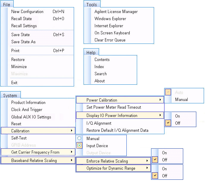
The following illustration shows the menu bar for the PXB user interface.
Select a command from the displayed menus for a description of the command.
Displays the  Configuration Browser
where you can view all of the available configurations based on the installed
licenses and hardware. When you select a configuration, the corresponding
block diagram is displayed.
Configuration Browser
where you can view all of the available configurations based on the installed
licenses and hardware. When you select a configuration, the corresponding
block diagram is displayed.
Recalls a previously-saved system configuration (.pxb) file, which contains block settings, configuration settings, and external device information.
Select Recall State to display the Open dialog box, which allows you to navigate to and select a file. Once the file is selected, it is displayed in the File name: box.
Click the Open button to recall the file. The information specific to the recalled configuration file is loaded and displayed in the PXB user interface with the information specific to the recalled configuration file. A warning message is displayed if there is a conflict between current and recalled instrument addresses.
|
|
A recalled configuration will also be applied to the PXB hardware. If the appropriate licenses for the hardware are not available, the recall will fail. |
Recalls previously-saved settings,independently of the entire state.
|
|
If the current configuration is not the same as the one saved in the .pxb file, a message will appear, advising the user of the condition. |
Saves all loaded configuration settings, block settings, and external device information to the file name and extension that you used when you last performed a recall or save.
|
|
Each time you click Save, your original file is overwritten. To avoid overwriting your original file, click Save As, and enter a new file name. |
Opens the Save As dialog box, which allows you to save the loaded configuration settings, block settings, and external device information as a configuration (.pxb) file. The PXB firmware does not support partial saves.
Opens the Print dialog box, which allows you to select a printer, set its properties, and print the active window of the PXB user interface. The PXB firmware does not support printing to a file.
|
|
Before printing, maximize the PXB application to avoid printing the desktop in the background. |
Returns the PXB user interface to its previous state.
Sends the PXB application to an icon on the Windows task bar. Click the icon to restore the PXB user interface and make it the active window.
Resets the PXB user interface to its maximum size.
Exits and closes the PXB user interface.
Displays the System Information and the Hardware Information tabs.
On the System Information tab, you can view the PXB system information, including the instrument's model number, serial number, firmware version, machine name, and host ID.
On the Hardware Information tab, you can view the assembly names and their corresponding product numbers, serial numbers, revisions, and hardware ID numbers.
Displays the Clock and Trigger settings in the parameter view for setup of the PXB's Master Trigger and Reference.
Opens the Glolbal AUX IO Settings window. You can also access the Global AUX IO Settings window by clicking the button at the bottom of the AUX IO Summary window.
Resets the instrument's settings to the factory default settings.
Power
Calibration
Ensures accurate power for the current configuration. Power calibration
is necessary to determine the waveform RMS voltage into the AWGN block
or into the signal generator. Power calibration operates on the currently
configured setup. Specifically when using
fading or AWGN, ensure that they are enabled and all settings are properly
set prior to
initiating the power calibration.
The AWGN block requires the input waveform RMS voltage to accurately scale the noise to produce the desired signal to noise ratio (SNR).
The ESG/MXG requires the input waveform RMS voltage so that it can deliver accurate output power. Once this value has been loaded into the signal generator, you can set the Power search mode to Auto on the signal generator, and every time you change the frequency or amplitude, the signal generator will do a power search to re-establish the correct output. You can also change the output amplitude using the Runtime Scaling property which does not require executing a power search.
Power calibration can be set to Auto or Manual.
Auto
In auto (default mode), a power calibration will be initiated each time a waveform is played. In some instances, executing a manual calibration may be sufficient as power calibration may be a time-consuming process (up to 10 minutes) depending on the complexity of the configuration and downloaded waveforms.
Manual
A manual power calibration
should be executed any time you perform an action that changes the
|
|
If the power calibration is set to manual, it will remain manual until it is changed to Auto. |
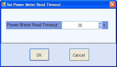
Set
Power Meter Read
Displays a
dialog box where you can set the time (in seconds) for the power meter to obtain
a valid reading before it generates a
time
out error.
Display IO Power Information
Enables or disables the IO Power Information tab.
On
When enabled (On), the IO Power Information tab appears in the main Block Diagram group of tab pages. Each assigned IO port assigned in your loaded configuration will display on the page; however, the input and output power fields will be empty until a power calibration is performed.
Off (default)
When disabled, the IO Power Information tab is hidden from view.
I/Q
Alignment
Calibrates the analog I/Q outputs of all I/O boards after a configuration
is loaded. I/Q Alignment removes the I/Q offset gain and quadrature errors,
which will improve baseband signal quality. This calibration needs to
be performed if there is a ±
5 degrees Celsius temperature change or every 24 hours. (This calibration
takes precedence over the factory-supplied calibration data.)
|
|
Presetting the instrument, closing the user interface, or cycling the power restores the default settings. To optimize your calibration data, run I/Q Alignment each time you restart the application. |
Restore
Default I/Q Alignment Data
Restores the factory-supplied I/Q alignment data.
Accesses the self test menu from which you can select tests to verify the functionality of each of the PXB baseband and I/O board assemblies. These self tests verify power supply voltages, internal clock signals, and data signals on each of the board assemblies and are used to identify a faulty assembly. Interconnect and system level tests verify the functionality between specific boards and their interfaces.
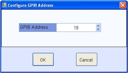
Displays the Configure
GPIB Address dialog box
where you can view and set the GPIB address of the PXB using the up and
down arrows in the dialog box, or by using the PXB's front panel keys.
When communicating with the PXB remotely, this address must be set in
the user interface before you can connect to it; there is no SCPI command
for setting this address.
This group of menu selections controls the carrier frequency couplings between external input devices and external output devices. This selection is saved and recalled in the “*.pxb” settings file and is automatically initialized at Load Configuration time. The default selection is determined at Load Configuration time, based on the configured input and output devices and whether the devices have a carrier frequency.
The carrier frequency is provided by the user. This is the default which is initialized at Load Configuration time if no input devices have a carrier frequency and no output devices have a carrier frequency. Each node in the block diagram that has a carrier frequency becomes read/write and the carrier frequency value at each node is provided by the user independently of all other external device Input nodes, fader Master Setup nodes, and external device Output nodes in the Block Diagram.
Input Device (default selection, if input device with CF is present)
The carrier frequency is provided from the input device. This is the default which is initialized at Load Configuration time if at least one external input device has a carrier frequency. This menu item is disabled if there are no input devices that have a carrier frequency.
The carrier frequency is provided from the output device. This is the default which is initialized at Load Configuration time if no input devices have a carrier frequency and at least one output device has a carrier frequency. This menu item is disabled if there are no output devices that have a carrier frequency.
This group of menu items controls the behavior of the PXB's Baseband Relative Scaling set of features.Use the power and runtime scaling settings in the Baseband Relative Power tab in conjunction with these controls.
Enforce Relative Scaling determines PXB’s behavior when a BBG’s Output RMS changes. If Enforce Relative Scaling is Off, then PXB will change the Actual Relative Power value in the Relative BBG Power panel after power calibration is complete. In its On state, when a BBG’s Output RMS changes, PXB will change its Runtime Scaling so the desired Relative Power remains unchanged. If the change would cause Runtime Scaling to clip, the PXB will set the Runtime Scaling to the clipped value and update the Output Power and Actual Relative Power to reflect the current Output RMS and relative power.
Default: On
Optimize for Dynamic Range determines PXB’s behavior how to do the relative BBG Scaling. It is applied when “Enforced Relative Scaling” is “On”. It has no effect if “Enforced Relative Scaling” is “Off”. If “Enforced Relative Scaling” is “On” and Optimize for Dynamic Range is On, then Runtime Scaling for each BBG will be adjusted to maintain the requested relative powers and also minimize the amount of scaling (minimize the amount of lost dynamic range). That means that the maximum Runtime Scaling setting among BBGs will be adjusted to 0.
Default: On.
Launches the
Launches an instance of Microsoft Windows Explorer.
Launches an instance of Microsoft Internet Explorer.
Displays the on-screen keyboard. The on-screen keyboard is a graphical computer keyboard that enables you to touch or click (if using a mouse) keys on a virtual QWERTY keyboard. It functions like the external keyboard, allowing you to enter text into any field that accepts alphanumeric data in the application. The on-screen keyboard can also be launched (or removed) by pressing the Keyboard key at the top, right side on the PXB's front panel.
Clears the errors messages displayed in the error log and re-reports
any unresolved errors. (Click the icon
at lower left corner of the user interface to display all of the errors
logged since the error queue was last cleared.) Refer to Error and Status Bar for additional information
on the error messages displayed in the error queue.
Opens the Help System and displays the index utility.
Opens the Help System and displays the search utility.
Displays the version and release date of the software.