The Agilent N9010A EXA, N9020A MXA, or the N9030A PXA signal analyzer is used as an RF down converter to convert a 25 MHz or 40 MHz RF modulation bandwidth signal (depending on installed option) to a digital baseband IQ signal . Refer to Register External Instrument for firmware revision requirements.
They provide a method of performing RF-to-RF fading and MIMO measurements allowed only in the PXB's external input (ext in) configurations. The PXB firmware sets the signal analyzer to IQ Analyzer (Basic) mode and uses signal analyzer only in this mode.
Optimizing the MXA provides a procedure and discussion of how to maximize the MXA's dynamic range for use as an input to the PXB.
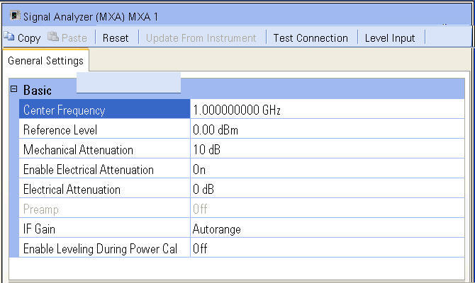
The Signal Analyzer setup pane is comprised of five buttons and one tab which are located at the top of the page.
Click a button in the graphic below to link to the button description.
Click the tab in the graphic below to link to the settings descriptions for the tab.
The General Settings tab is used to set up the signal analyzer.
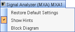
The name of the block is
displayed at the top of the setup pane. This name was assigned when the
signal analyzer was registered during the signal analyzer setup and displayed
in the External
Instrument Table and the block diagram. When the  name is selected,
additional choices, including a selection to show or hide the Hints area,
are displayed.
name is selected,
additional choices, including a selection to show or hide the Hints area,
are displayed.
There are also several buttons located immediately below the signal analyzer name. The following is a description of each button:
There are five buttons located immediately below the Playback [n]: BBG name. The following is a description of each button:
Reset presets the external instrument (signal
analyzer) and then applies the current PXB signal analyzer user interface
settings to the signal analyzer.
|
|
Selecting Reset has no effect on the signal analyzer values that are displayed. You must select Update From Instrument to see the current signal analyzer values in the PXB user interface. |
Update From Instrument loads the parameter settings from the signal analyzer to the PXB user interface.
Test Connection tests the LAN or GPIB connection between the PXB and the signal analyzer. If the test connection fails, refer to the external instrument setup dialog box to verify that all LAN/GPIB addresses are valid. Ensure that all cables are securely connected to the correct input/output connectors on the respective instruments.
Level Input levels the signal analyzer input by adjusting input attenuation, maximizing the signal level to the ADC for best performance. Leveling is done once by reducing input attenuation until an ADC over-range is detected, then increasing attenuation 2 dB. Leveling does not automatically control IF Gain or Preamp.