
The maximum sample rate depends on licensing, hardware system, port configuration, logic type, and signal mapping.
This cell determines the type of memory the waveform will be played from. Your choice will depend on the waveform size and the desired playback sample rate.
|
Optimize Depth |
With this choice, playback will occur directly from the hard drive. Waveform file size is limited only by the available space on the hard drive. |
|
Optimize Speed |
With this choice, the waveform file contents are copied to the DRAM on board the N5101, and playback occurs from the DRAM. Waveform file size is limited by the available DRAM. |
|
Automatic Selection |
With this choice, the waveform file will load into and play back from DRAM if the waveform will fit (<=512 MSamples). Otherwise, playback will occur directly from the hard drive. |
This cell controls the sample rate for waveform playback via the ESG/PSG sample rate setting. This sample rate setting also appears in the playback Waveform Setup table, for user convenience.
|
|
The maximum sample rate depends on licensing, hardware system, port configuration, logic type, and signal mapping. |
This cell controls how the start trigger is received, either from the play button or a hardware trigger.
Note: Once started, all options except source control are disabled when playback from the hard disk.
|
Hardware |
With this choice, the streaming process waits and begins playback upon receiving a trigger signal via one of the N5101A SMB ports. See GPIO Port Assignment for more information on configuring SMB ports. |
|
Software |
With this choice,
the streaming process waits and begins playback when the user clicks the
play |
When Playback is through an ESG/PSG, the minimum value is 0 and latency is not reported.
This cell controls action taken when the end of the waveform is reached.
|
Continuous |
This
choice plays the waveform in a continuous loop until the Stop |
|
This choice plays the waveform a specified number of times and then reloads the buffers. The number of times is determined by the value set in the Loop Count cell. |
This cell controls the number of loops played when the On Last Sample cell is set to Count.
This cell controls IQ state after the last sample of the waveform is played. This cell becomes available when the On Last Sample cell is set to Count. This setting is only available in RF playback mode.
|
Hold Last Sample Value |
This choice holds the last I and Q sample value on the output until the next waveform is played. |
|
Hold Zero |
This choice sets the output value to zero when the waveform has completed playing. |
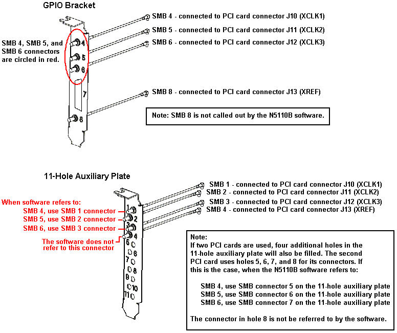
These cells assign input/output indicator and triggering signals to
the SMB 4, SMB 5, and SMB 6 connectors on the GPIO port.
(View the SMB connector locations for both styles of the PCI card brackets)
The N5101A Baseband Studio PCI Card has an attached bracket that is
also located on the rear panel of your PC. The connectors on this bracket
are used by the N5110B Baseband Studio for Waveform Capture and Playback
software when SMB 4, SMB 5, and SMB 6 is called out. There are two versions
of this bracket.
Click here for an explanation of these brackets
The GPIO Bracket is the original bracket. When the SMB connector naming/numbering conventions for the N5110B software was developed, this bracket was the only bracket available. Therefore, when connectors SMB 4, SMB 5, and SMB 6 are called out in the software, the software is referring directly to this bracket and its connectors.
The 11-Hole Auxiliary Plate is a more recent version of the bracket. One of it's purposes is to provide enough SMB connectors for two PCI cards on a single bracket. With places for as many as eleven SMB connectors, the naming/numbering convention for this new bracket did not follow the naming/numbering convention for the original GPIO bracket. Therefore, when connectors SMB 4, SMB 5, and SMB 6 are called out in the software, you should refer to the illustration for the correct connections for this bracket and connectors.
Note: These brackets are installed when the PCI card is installed in your PC. The most current version of this installation procedure is: N5101A Baseband Studio PCI Card Installation Guide
The choices for SMB 4-6 are described below:
|
Off |
This choice assigns no signal to the SMB connector, effectively turning the port off. |
|
Start Trigger |
This choice sets the GPIO connector as a start trigger input. The signal has a TTL level with a nominal impedance of 1.0 kohms. Note: You can only assign the start trigger input to one port at a time. If you select Start Trigger for an SMB port and it is already assigned to another port, the software will automatically turn off the previously assigned port. |
|
Underflow Indicator |
This choice sets the GPIO connector as the underflow indicator output. The signal has a TTL level with a nominal impedance of 1.0 kohms. |
|
Playing Indicator |
This choice sets the GPIO connector as the playing indicator output. The signal has a TTL level with a nominal impedance of 1.0 kohms. |
|
Playback Completed Indicator |
This choice sets the GPIO connector as the playback completed indicator output. The signal has a TTL level with a nominal impedance of 1.0 kohms. |
|
Ready to Playback |
This choice sets the GPIO connector as the ready indicator output. The signal has a TTL level with a nominal impedance of 1.0 kohms. |
These cells set the active states for signals assigned to the SMB connectors. The SMB Polarity cells are grayed out (not active) for SMB ports that are set to off.
|
Positive |
This choice sets the software to expect an active-high start trigger input signal or to send an active-high output signal, depending on the SMB signal assignment. |
|
Negative |
This choice sets the software to expect an active-low start trigger input signal or to send an active-low output signal, depending on the SMB signal assignment. |
Markers designate specific points within a waveform. These are digital signals that are aligned with the analog waveform and are available at the rear panel connectors. Markers 1 and 2 are routed to the event connector that corresponds to the marker number; markers 3 and 4 are routed to the Event 3 and Event 4 pins on the AUXILIARY I/O connector, respectively.
For more information on markers, refer to the signal generator documentation.
These cells determine the source of the marker data. Each active marker has the following menu of choices:
The marker choices are described below:
|
I_bit_0 |
This is a user-provided marker. The marker is encoded in the waveform's I channel data using bit 0. | |
|
I_bit_1 |
This is a user-provided marker. The marker is encoded in the waveform's I channel data using bit 1. | |
|
Q_bit_0 |
This is a user-provided marker. The marker is encoded in the waveform's Q channel data using bit 0. | |
|
Q_bit_1 |
This is a user-provided marker. The marker is encoded in the waveform's Q channel data using bit 1. | |
|
Periodic
|
With this choice, the user specifies the sample and duration where the marker will be active. When Periodic is selected, the Pulse Start, Pulse Width, and Pulse Period cells appear in the marker table. To specify a periodic marker, you must set these three parameters. | |
|
|
Pulse |
This choice sets the sample on which the marker becomes active (on). This cell only appears when Marker Source is set to Periodic. |
|
|
Pulse |
This choice determines the width of the active marker, in samples. This cell only appears when Marker Source is set to Periodic. |
|
|
Pulse |
This choice sets the total number of samples in the marker cycle (on plus off). This cell only appears when Marker Source is set to Periodic. |
|
Zero Detect |
With this choice, the marker is active when I and Q are both zero; otherwise, marker is not active. | |
|
Range Detect |
With this choice, the user specifies the range in which the marker will be active. When Range Detect is selected, the Range Data, Range Limit Relationship, Range Limit 1, and Range Limit 2 cells appear in the marker table. To specify a periodic marker, you must set these three parameters. | |
|
|
Range |
This choice sets the source of data used to apply the range relationship to in the range defined dynamic marker generator. This field only appears when Marker Source is set to Range Detect. |
|
|
Range Limit Relationship |
This choice sets the relationship between the first and second limits of the range defined dynamic marker generator. This field only appears when Marker Source is set to Range Detect. |
|
|
Range |
This choice sets the first limit in the range defined dynamic marker generator. This field only appears when Marker Source is set to Range Detect. |
|
|
Range |
This choice sets the second limit in the range defined dynamic marker generator. This field only appears when Marker Source is set to Range Detect. |
|
|
Off |
This choice turns off the selected marker. |
|
|
In RF playback mode, all marker information is transmitted to the Signal Generator (ESG/PSG) using the least significant bits of the I and Q waveform data lines. If no markers are enabled, all I and Q waveform data samples are transmitted using 16 bits. If marker 1 and/or marker 2 are used, the waveform data is transmitted using 15 bits to the signal generator. If marker 3 and/or 4 are used, the waveform data is transferred using 14 bits. |
This cell delays the individual marker by 0-1000 samples. The resolution of time delay will be rounded to the nearest 1/Sample Rate.
Note: The time delay is determined by the sample rate. If the time delay is set and the sample rate is changed, the number of samples delayed will change to keep the time delay constant (if the resulting delay is out of range, time delay will be clipped at the limit). If Delay Unit is set to Samples and the rate is changed, the sample delay will remain constant and the time delay will be updated based on the new sample rate. The default will be to hold the sample delay constant.
This cell sets the delay units to either samples or uSec.
|
Samples |
This choice holds the last I and Q sample value on the output until the next waveform is played. |
|
Time |
This choice sets the output value to zero when the waveform has completed playing. |
This cell inverts the polarity of the selected marker.
 button in the software's tool bar.
 button on the tool bar is pressed.