Channel Setup – Advanced Uplink Carrier
Advanced uplink carriers consist of the following:
-
Adv W-CDMA/HSPA+ UL Rel 10
-
Adv W-CDMA/HSPA+ UL Rel 11 (MEU Option U03 or greater only)
This topic describes the parameters available in the advanced uplink
 channel setup node.
Channel Configuration Summary Table
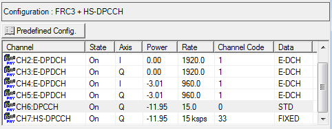
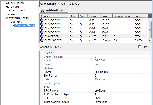
This table enables you to view the key parameters for each channel in a carrier. Unlike the channel configuration summary table for the basic uplink carrier selections, the advanced carrier does not allow channel additions or deletions. All of the advanced channel configurations (RMC, FRC, CELL_FACH) are created in accordance with the 3GPP standards.
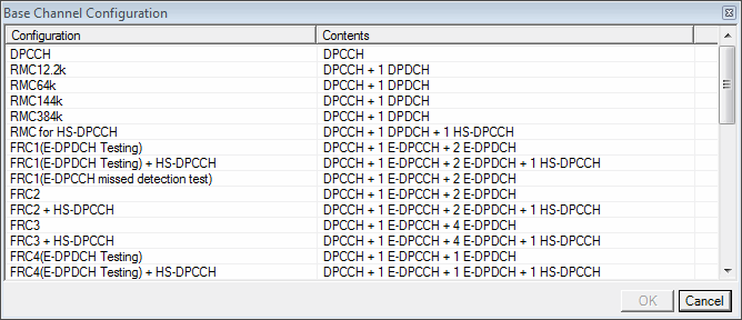
 This button opens a window of predefined channel configuration selections
according to the selected carrier type:
 Adv W-CDMA/HSPA+
UL Rel 11 (MEU Option U03 or greater only)
Double-clicking a configuration replaces the current configuration in the setup table. Select the carrier type from the Waveform or Carrier views.
3GPP
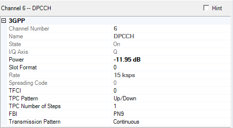
This table enables you to configure 3GPP channel parameters. The figure above shows the parameters for the DPCCH channel. These parameters will vary according to the channel type. For example, E-DPCCH, HS-DPCCH, DPDCH, and E-DPDCH all have different parameter sets than what is shown in the figure above. Toggle a channel type below to see a list of its associated parameters. Then click a channel parameter to jump to a description.
|
|
|
|
|
|
|
|
|
|
This cell displays the selected channel type.
State
This cell only provides information (grayed out) on the selected channel. For the E-DPDCH, the software uses the Channel Number, TTI, E-TFCI Table Selection, E-TFC Index, E-DPDCH Maximum Channelization Codes, Modulation Capacity and PLnon-max to determine the State.
State (Alternate)
On the E-DPDCH, this cell only provides information (grayed out) to use when ALT (Alternate parameter settings) is selected in the TTI Pattern Data Type Entry window. For the E-DPDCH, the software uses the Channel Number, TTI, E-TFCI Table Selection (Alternate), E-TFC Index (Alternate), E-DPDCH Maximum Channelization Codes, Modulation Capacity and PLnon-max to determine the State (Alternate).
Channel Number
View the channel number of the displayed parameters.
Name
View the channel type.
I/Q Axis
This cell only provides information (grayed out) on the selected channel data path as to whether it is on I or Q.
-
When MIMO with 4 Tx antennas is not configured and the Secondary Cell Enabled is > 3, I/Q Axis weill be I&Q.
-
When MIMO with 4 Tx antennas is configured and 2nd or 3rd Secondary Cell is active, I/Q Axis will be I&Q.
-
When Nmax-dpcch is 0,1,3,5, I/Q Axis will be Q.
-
When Nmax-dpcch is 2, 4, 6, I/Q Axis wil be I.
Power
Range: −60 to 0 dB
Enter the channel power level relative to the carrier power.
On E-DPDCH, the software ensures that the power values among the channels are maintained in accordance with the 3GPP standards. For example using the FRC 3 channel configuration, the standard states that a power difference of -3.01 dB be maintained between the E-DPDCH with SF2 and the E-DPDCH otherwise. With the E-DPDCH with SF2 set to 0 dB, the power level of the E-DPCCH otherwise is -3.01 dB. With the E-DPDCH otherwise set to -60 dB, the DPDCH minimum power is -56.99 dB. This means, even though the minimum power range value is -60 dB, the E-DPDCH with SF2 cannot go lower than -56.99 dB.
Power (Alternate)
Range: −60 to 0 dB
On the E-DPDCH, enter the channel power level relative to the carrier power to use when (Alternate parameter settings) is selected in the TTI Pattern Data Type Entry window for a user-defined pattern. This cell is grayed out if the data entry type is MAIN ALL (no alternate parameter settings).
When the waveform encounters a slot set to during waveform playback, it ignores the Power value as the channel power and instead uses the value for the channel power. Conversely when a slot is configured as or (all slots set to MAIN), the waveform uses the value.
On E-DPDCH, the software ensures that the power values among the channels are maintained in accordance with the 3GPP standards. For example using the FRC 3 channel configuration, the standard states that a power difference of -3.01 dB be maintained between the E-DPDCH with SF2 and the E-DPDCH otherwise. With the E-DPDCH with SF2 set to 0 dB, the power level of the E-DPCCH otherwise is -3.01 dB. With the E-DPDCH otherwise set to -60 dB, the DPDCH minimum power is -56.99 dB. This means, even though the minimum power range value is -60 dB, the E-DPDCH with SF2 cannot go lower than -56.99 dB.
Slot Format
Range: 0 to 4
Default: 0
This cell applies to the DPCCH. To enter a value, highlight the existing value and enter the new slot number. The slot format determines the number of transmitted TFCI bits in addition to other control bits.
Rate
This cell only provides information (grayed out) on the symbol rate for the selected channel.
For the E-DPDCH, the software uses the Channel Number, TTI, E-TFCI Table Selection, E-TFC Index, E-DPDCH Maximum Channelization Codes , Modulation Capacity and PLnon-max to determine the Symbol Rate.
For the HS-DPCCH, the Rate value can be 15 ksps or 30 ksps, which is determined by Secondary Cell Enabled and MIMO settings. For more information, refer to TS 25.212 Table 15C.4.
-
When Secondary Cell Enabled is 0 or 1, HS-DPCCH Slot Format is 0 and Rate is 15 ksps.
-
When Secondary Cell Enabled is 3, HS-DPCCH Slot Format is 1 and Rate is 30 ksps.
-
When Secondary Cell Enabled is 2 and no cell is configured as MIMO, HS-DPCCH Slot Format is 0 and Rate is 15 ksps.
-
When Secondary Cell Enabled is 2 and at least one cell is configured as MIMO, HS-DPCCH Slot Format is 1 and Rate is 15 ksps.
Rate (Alternate)
On the E-DPDCH, this cell only provides information (grayed out) on the symbol rate for the alternate setting to use when ALT (Alternate parameter settings) is selected in the TTI Pattern Data Type Entry window. The software uses the Channel Number, TTI, E-TFCI Table Selection (Alternate), E-TFC Index (Alternate), E-DPDCH Maximum Channelization Codes, Modulation Capacity and PLnon-max to determine the Symbol Rate (Alternate).
Spreading Code
This cell only provides information (grayed out) on the spreading code for the selected channel.
For the E-DPDCH, the software uses the Channel Number, TTI, E-TFCI Table Selection, E-TFC Index, E-DPDCH Maximum Channelization Codes, Modulation Capacity and PLnon-max to determine the Spreading Code.
For the HS-DPCCH, the Spreading Code is defined by Rate and Nmax-dpdch (which is the number of DPDCH) as the following table. See 4.3.1.2.2 in TS 25.213 for more details.
| Nmax-dpdch | Slot Format = 0 | Slot Format = 1 |
|---|---|---|
| 0 | 33 | 16 |
| 1 | 64 | 32 |
Spreading Code (Alternate)
On the E-DPDCH, this cell only provides information (grayed out) on the spreading code for the alternate setting to use when ALT (Alternate parameter settings) is selected in the TTI Pattern Data Type Entry window. The software uses the Channel Number, TTI, E-TFCI Table Selection (Alternate), E-TFC Index (Alternate), E-DPDCH Maximum Channelization Codes, Modulation Capacity and PLnon-max to determine the Spreading Code (Alternate).
TTI
Choices: 2 ms | 10 ms
On the E-DPCCH and E-DPDCH, double click or use the pull-down menu to set the TTI for the selected channel. The TTI information effects the Tx length of the TTI Pattern, even if is set to . The software ensures that all the TTI values of the channels are set to the same value.
The information in this cell is only relevant when the E-DCH is the data selection for the Data cell.
TTI Pattern
Choices: Main All | User
This cell sets the TTI pattern for the E-DPCCH and
E-DPDCH. When you click the cell, a dialog box button ( ) appears and provides access to the TTI
Pattern Selection dialog box where you can select or create TTI data
patterns. Selecting User activates the data editor enabling you to enter
the state and power, and designate main or alternate of any slot up to
15,330 slots. Select all main parameters (Main All) or use a user-defined
file to assign either the main or alternate parameter settings for E-TFCI
table selection, E-TFC index, and Power.
The Number of Frames cell in the advanced carrier view determines the length of the waveform. If the configured pattern length exceeds the waveform length, the software ignores the excess pattern slots.
DCH1 TTI / DCH2 TTI
Choices: 10 ms | 20 ms | 40 ms | 80 ms
On the DPDCH, double click or use the pull-down menu to set the DCH TTI. The information in these cells is only relevant when the DCH is the data selection for the Data cell.
DCH TTI is the transmit time interval for the data, which is the product of block size (determined by the software) and number of blocks. The TTI determines over how many consecutive frames the transport layer data is distributed. For example, since each frame is 10 milliseconds, a TTI of 40 milliseconds distributes the data over four frames.
DCH1 Rate Matching Attribute / DCH2 Rate Matching Attribute
Range: 1 to 256
Default: 256
On the DPDCH, enter a DCH rate matching attribute. The information in these cells is only relevant when the DCH is the data selection for the Data cell.
DCH1 Number of Blocks / DCH2 Number of Blocks
Range: 0 to 512
On the DPDCH, enter a DCH number of blocks. At least one of the DCH number of blocks should be set to more than 0. The information in these cells is only relevant when the DCH is the data selection for the Data cell.
DCH1 Block Size / DCH2 Block Size
This cell only provides information (grayed out) on the DCH block size in the current RMC channel configuration, which complies with the 3GPP standards. The information in these cells is only relevant when the DCH is the data selection for the Data cell.
DCH1 CRC / DCH2 CRC
This cell only provides information (grayed out) on the DCH cyclic redundancy bits in the current RMC channel configuration, which complies with the 3GPP standards. The information in these cells is only relevant when the DCH is the data selection for the Data cell.
DCH1 Coding Type / DCH2 Coding Type
This cell only provides information (grayed out) on the DCH coding type in the current RMC channel configuration, which complies with the 3GPP standards. The information in these cells is only relevant when the DCH is the data selection for the Data cell.
E-TFCI Table Selection
Choices: 0 | 1
On the E-DPCCH and the E-DPDCH, enter the value for this cell that selects the 3GPP standards Annex B table ( B.1 Table 0, B.2 Table 1, B.2a. Table 2, B.2b Table 3, B.3 Table 0 or B.4 Table 1) for the cell value. Each table lists the E-TFC index values, which set the transport block size (bits) for the E-DCH. With the TTI set to 2 ms and the Modulation Capacity set to 16QAM (2x4PAM), the software internally increases the table value by two. For example, if the displayed table value is one and the previously stated conditions exist, the actual table value is three. Because this is done internally, the increased value does not appear in the UI. The software ensures that the same E-TFCI table selection value applies to both the E-DPDCH and E-DPCCH.
The table associated with the description shows the default value for the supported FRCs.
E-TFCI Table Selection (Alternate)
Choices: 0 | 1
Default: 0
On the E-DPCCH and the E-DPDCH, enter the value for this cell that selects the 3GPP standards Annex B table ( B.1 Table 0, B.2 Table 1, B.2a. Table 2, B.2b Table 3, B.3 Table 0 or B.4 Table 1) for the cell value. Each table lists the E-TFC index values, which sets the transport block size (bits) for the E-DCH. With the TTI set to 2 ms and the Modulation Capacity set to 16QAM (2x4PAM), the software internally increases the table value by two. For example, if the displayed table value is one and the previously stated conditions exist, the actual table value is three. Because this is done internally, the increased value does not appear in the UI. The software ensures that the same E-TFCI table selection value for the alternate setting applies to both the E-DPDCH and E-DPCCH.
This cell is grayed out while the TTI Pattern is . Select to make the cell active. The software uses this value for the slots selected as in the TTI Pattern.
The table associated with the description shows the default value for the supported FRCs.
E-TFC Index
On the E-DPCCH and E-DPDCH, enter the E-TFC index value. On the E-DPCCH, the information in this cell is only relevant when is the data selection for the Data cell.
The index number corresponds to a value that is the number of bits for the E-DCH (E-DPDCH transport channel) in accordance with the 3GPP standards Annex B tables, B.1 Table 0, B.2 Table 1, B.2a. Table 2, B.2b Table 3, B.3 Table 0 or B.4 Table 1. The following table shows the default index values for the supported FRCs along with their associated transport block size and E-TFCI table values. The software ensures that the same E-TFC index value applies to both the E-DPDCH and E-DPCCH.
Default E-TFC Index Value and E-TFCI Table Selection to E-DCH Block Size
|
FRC Selection |
E-TFC Index |
Transport Blk Size (Bits) |
Table Selection |
|---|---|---|---|
|
FRC1 (E-DPDCH testing) |
42 |
2706 |
B.2 2 ms TTI E-DCH Transport Block Size Table 1 |
|
FRC1 (E-DPDCH testing) + HS-DPCCH |
|||
|
FRC1 (E-DPCCH missed detection test) |
|||
|
FRC2 |
70 |
5412 |
|
|
FRC2 + HS-DPCCH |
|||
|
FRC3 |
94 |
8100 |
|
|
FRC3 + HS-DPCCH |
|||
|
FRC4 (E-DPDCH Testing) |
41 |
5076 |
B.4 10 ms TTI E-DCH Transport Block Size Table 1 |
|
FRC4 (E-DPDCH testing) + HS-DPCCH |
|||
|
FRC4 (E-DPCCH missed detection test) |
|||
|
FRC5 |
69 |
9780 |
|
|
FRC5 + HS-DPCCH |
|||
|
FRC6 |
118 |
19278 |
|
|
FRC6 + HS-DPCCH |
|||
|
FRC7 |
7 |
690 |
|
|
FRC7 + HS-DPCCH |
|||
|
FRC8 (Non E-DPCCH boosting) |
96 |
16218 |
B.2b 2ms TTI E-DCH Transport Block Size Table 3* |
|
FRC8 (Non E-DPCCH boosting) + HS-DPCCH |
|||
|
FRC8 (E-DPCCH boosting) |
* When using 16QAM (2X4PAM) and a 2 ms TTI, the software internally increases the table value by two per the 3GPP standards. Because this is an internal process, the table value increase does not show in the user interface.
E-TFC Index (Alternate)
On the E-DPCCH and E-DPDCH, enter the E-TFC index value. On the E-DPCCH, the information in this cell is only relevant when is the data selection for the Data cell.
The index number corresponds to a value that is the number of bits for the E-DCH (E-DPDCH transport channel) in accordance with the 3GPP standards Annex B tables, B.1 Table 0, B.2 Table 1, B.2a. Table 2, B.2b Table 3, B.3 Table 0 or B.4 Table 1. The software ensures that the same E-TFC index value applies to both the E-DPDCH and E-DPCCH.
This cell is grayed out while the TTI Pattern is . Select to make the cell active. The software uses this value for the slots selected as in the TTI Pattern.
The table associated with the description shows the default index values for the supported FRCs.
E-DPDCH Maximum Channelization Codes
On the E-DPDCH, this cell only provides information (grayed out) on the spreading factor and number of E-DPDCHs to be used in the standard-based configuration. The maximum channelization codes are used together with the E-DCH configuration and PLnon-max parameter to automatically calculate the physical channel codes as defined in the standards.
Modulation Capacity
Choices: QPSK (2xBPSK) | 16QAM (2x4PAM)
On the E-DPDCH, double click or use the pull-down menu to set the modulation capacity. If the Modulation Capacity is set to 16QAM (2x4PAM) and TTI is set to 2 ms, the E-TFCI table selection is internally increased by 2.
PLnon-max
Range: 0.44 to 1
Default: 0.44
On the E-DPDCH, enter the PLnon-max value. The PLnon-max is used together with the E-DPDCH Maximum Channelization Codes and E-DCH configuration to automatically calculate the physical channel codes as defined in the 3GPP standards.
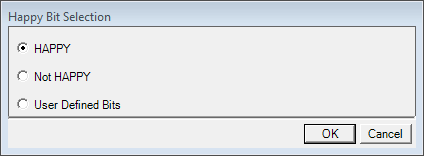
Happy Bit
Choices: HAPPY | Not HAPPY | User Defined Bits
Default: HAPPY
This bit is present during the uplink transmission
of the E-DPCCH when it uses the
data selection. When you click the cell, a dialog box button ( ) appears and provides access to the Happy Bit Selection
  dialog box
from where you make the selection.
With the dialog box selection of User Defined Bits, the software allows the customized setting of each bit to be HAPPY or Not HAPPY for up to 65,536 E-DPCCH subframes or frames. The Happy bit notifies the basestation as to whether the UE is satisfied (happy) with the current Serving Grant based on available data rate, power, and capacity.
TFCI
Range: 0 to 1023
Default: 0
On the DPCCH, enter a TFCI code. The number of TFCI bits transmitted is dependent on the slot format. The TFCI bits inform the basestation of the UE's transport channel formatting.
TPC Pattern
Choices: Up/Down | Down/Up | All Up | All Down | User Defined Bits
Default: Up/Down
This cell sets the TPC (transmit power control) pattern.
This pattern instructs the base station to increase or decrease its power
in 1 dB increments. When you click the cell, a dialog box button ( ) appears and provides access to the TPC Entry window
where you can select from the choices
TPC Number of Steps
Range: 1 to 80
Default: 1
This cell sets the number of up and down power steps for the selections Up/Down and Down/Up. For example with this cell set to 20 and the TPC Pattern set to Up/Down, the signal generator transmits a power pattern that tells the basestation to step-up the power up in 1 dB increments for 20-steps and then down for 20-steps. The signal repeats this pattern until the parameter changes or the signal terminates.
FBI
Choices: PN9 | PN15 | User Defined Bits
Default: PN9
This cell sets the FBI pattern for the DPCCH. When
you click the cell, a dialog box button ( ) appears and provides access to the Data Source Selection window where you can select
or create data patterns. Selecting User Defined Bits activates the data
editor enabling you to enter a binary value of any length up to 400,000
bits. If the software sees more bits than what it can use, it truncates
the data and discards the unused bits
The FBI bits are used to implement closed loop format diversity by controlling the phase, or phase and amplitude of the second antenna of the base station. The FBI bits are also used for site selection diversity transmit power control during a soft handoff. The slot format determines the number of FBI bits per slot.
Transmission Pattern
Choices: Continuous | User Defined Burst Pattern
Default: Continuous
This cell sets the transmission pattern for the DPCCH.
When you click the cell, a dialog box button ( ) appears and provides access to the Transmission Pattern Selection dialog box where
you can select or create data patterns. Selecting activates the data editor enabling you to
enter the state and the power of any slot up to 15,330 slots.
The Number of Frames cell in the advanced carrier view determines the length of the waveform. If the configured pattern length exceeds the waveform length, the software ignores the excess pattern slots.
For CELL_FACH channel configurations, this parameter is not visible, but is set to continuous by the software.
Data
Choices: PN9 | PN15 | DCH | E-DCH | STD | User Defined Bits
(The shown choices are a composite of the available choices, the actual choices vary by channel type.)
Default: Varies by channel type
When you click the cell, a dialog box button ( ) appears and provides access to Data Source Selection dialog box where you select
the data type. For channel configurations with multiple data channels,
if you change the data type on one data channel, the software changes
the other data channels to the same data type.
The E-DPDCH Data have four selections:
-
Continuous PN9 or PN15 sequences: The bit sequence is continuous between TX slots.
-
E-DCH: Coding data.
-
USER: A user-defined data pattern. If the data length is less than the TTI size, the data is repeated. If the data length is greater than the TTI size (depends on channel configuration), the user data is truncated at the data payload size that corresponds to one TTI length.
The diagram below illustrates the data flow for each data type with either 2 or 4 E-DPDCH States set to .

DCH1/DCH2
Choices: PN9 | PN15 | User Defined Bits
Default: PN9
When the DPDCH
cell selection is DCH, the software uses the two transport channels, DCH1
and DCH2, to provide the data. When you click the cell, a dialog box button
( ) appears and provides access to the Data Source Selection window where you can select
or create data patterns.
E-DCH
Choices: PN9 | PN15 | User Defined Bits
Default: PN9
When the E-DPDCH
cell selection is E-DCH, the software uses the transport channel to provide
the data. When you click the cell, a dialog box button ( ) appears and provides access to the Data Source Selection window where you can select
or create data patterns.
Modulation
This cell applies to the E-DPDCH and only provides information (grayed out) on the modulation type. It displays either BPSK or 4PAM. The software uses TTI, E-TFCI Table Selection, E-TFC Index, E-DPDCH Maximum channelisation codes, Modulation Capacity and PLnon-max to determine the modulation.
Modulation (Alternate)
This cell applies to the E-DPDCH and only provides information (grayed out) on the modulation type to use when ALT (Alternate parameter settings) is selected in the TTI Pattern Data Type Entry window. It displays either BPSK or 4PAM. The software uses TTI, E-TFCI Table Selection (Alternate), E-TFC Index (Alternate), E-DPDCH Maximum channelisation codes, Modulation Capacity and PLnon-max to determine the modulation.
Delta ACK
Range: 0 to 8
Default: 5
On the HS-DPCCH, enter the Delta ACK. The software defines the signaled value by using the Delta ACK, Delta NACK, Secondary Cell Enabled, MIMO or not, HARQ-ACK selection, and MIMO Type according to the following table. The signaled value is translated into the quantized amplitude ratios Ahs, in accordance with the 3GPP standards TS 25.213 Table 1A, to calculate the power of the HS-DPCCH slots carrying the HARQ Acknowledgment.
Some of the parameters mentioned above that affect the signaled value are only editable with a User-Defined HS-DPCCH Pattern. If left unedited, the software uses the default settings for these parameters.
Signaled Value to HS-DPCCH Parameters for the HARQ-ACK Field when Secondary Cell Active is 0 (from 3GPP TS 25.214 Table 2A)
| HARQ-ACK message sent in one time slot | Ahs equals the quantized amplitude ratio translated from |
|---|---|
| ACK | Delta ACK |
| NACK | Delta NACK |
|
PRE before single transport block or Post after a single transport block |
MAX(Delta ACK, Delta NACK ) |
| ACK/ACK | Delta ACK + 1 |
| NACK/NACK | Delta NACK + 1 |
|
ACK/NACK or NACK/ACK or PRE before dual transport block or Post after a dual transport block |
MAX( Delta ACK+1, Delta NACK+1) |
Signaled Value to HS-DPCCH Parameters for the HARQ-ACK Field when Secondary Cell Active is not 0 (from 3GPP TS 25.214 Table 2B)
| Secondary_Cell_Active | Condition | Ahs equals the quatized amplitude ratio translated from | ||
|---|---|---|---|---|
| Composite HARQ-ACK message(s) sent in one time slot contains... | ||||
| at least one ACK but no NACK | at least one NACK but no ACK | both ACK and NACK, or a PRE, or a POST | ||
| 1 | NA | Delta ACK + 1 | Delta NACK + 1 | MAX( Delta ACK+1, Delta NACK+1) |
| 2 | Secondary_Cell_Enabled is 2 and MIMO is not configured in any cell | Delta ACK + 1 | Delta NACK + 1 | MAX( Delta ACK+1, Delta NACK+1) |
| 2 | Secondary_Cell_Enabled is 2 and MIMO is configured in any cell | Delta ACK + 2 | Delta NACK + 2 | MAX( Delta ACK+2, Delta NACK+2) |
| 3 | NA | Delta ACK + 2 | Delta NACK + 2 | MAX( Delta ACK+2, Delta NACK+2) |
Delta NACK
Range: 0 to 8
Default: 5
On the HS-DPCCH, enter the Delta NACK. The software defines the signaled value with the Delta ACK, Delta NACK, HARQ-ACK selection, Secondary Cell Enabled, MIMO or not, and the MIMO Type according to the table in the Delta ACK description. The signaled value is translated into the quantized amplitude ratios Ahs in accordance with the 3GPP standards TS 25.213 Table 1A to calculate the power of the HS-DPCCH slots carrying HARQ Acknowledgment.
Some of the parameters mentioned above that affect the signaled value are only editable with a User-Defined HS-DPCCH Pattern. If left unedited, the software uses the default settings for these parameters.
Delta CQI
Range: 0 to 8
Default: 5
On the HS-DPCCH, enter the Delta CQI. The software defines the signaled value with the Secondary Cell Active, the MIMO Type and CQI Report according to the following table. The signaled value is translated into the quantized amplitude ratios Ahs in accordance with the 3GPP standards TS 25.213 Table 1A to calculate the power of the HS-DPCCH slots carrying CQI.
Some of the parameters mentioned above that affect the signaled value are only editable with a User-Defined HS-DPCCH Pattern. If left unedited, the software uses the default settings for these parameters.
The signaled value to HS-DPCCH parameters for the CQI field (Table 2C from 3GPP TS 25.214)
| Secondary_Cell_Active | Condition | Ahs equals the quatized amplitude ratio translated from | ||
|---|---|---|---|---|
| MIMO is not configured | MIMO is configured | |||
| CQI of Type A | CQI of Type B | |||
| 0 | NA | Delta CQI | Delta CQI+1 | Delta CQI |
| 1 | Secondary_Cell_Enabled is 1 and MIMO is not configured in any cell | Delta CQI+1 | N/A | N/A |
| 1 | Secondary_Cell_Enabled is 1 and MIMO is configured in any cell | Delta CQI | Delta CQI+1 | Delta CQI |
| 2 | Secondary_Cell_Enabled is 2 and MIMO is not configured in any cell | Delta CQI | N/A | N/A |
| 2 | Delta CQI+1 | N/A | N/A | |
| 2 | Secondary_Cell_Enabled is 2 and MIMO is configured in any cell | Delta CQI+1 | Delta CQI+2 | Delta CQI+1 |
| 3 | NA | Delta CQI+1 | Delta CQI+2 | Delta CQI+1 |
Ahs for Delta ACK
Range: 0.333 to 2
Default: 1
This cell applies to the HS-DPCCH and only provides information (grayed out) on the Ahs for Delta ACK. The software uses the Delta ACK to calculate the Ahs for Delta ACK in accordance with the 3GPP standards Table 1A.
Ahs for Delta NACK
Range: 0.333 to 2
Default: 1
This cell applies to the HS-DPCCH and only provides information (grayed out) on the Ahs for Delta NACK. The software uses the Delta NACK to calculate the Ahs for Delta NACK in accordance with the 3GPP standards Table 1A.
Ahs for Delta CQI
Range: 0.333 to 2
Default: 1
This cell applies to the HS-DPCCH and only provides information (grayed out) on the Ahs for Delta CQI. The software uses the Delta CQI to calculate the Ahs for Delta CQI in accordance with the 3GPP standards Table 1A.
ACK Power
Range: -60 dB to 0 dB
This cell applies to the HS-DPCCH and only provides information (grayed out) on the ACK power. The software uses Ahs for Delta ACK and the Power of the DPCCH to calculate the gain factor βhs for Delta ACK as follows, and then using the results, calculates ACK Power.
βhs = βcxAhs
NACK Power
Range: -60 dB to 0 dB
This cell applies to the HS-DPCCH and only provides information (grayed out) on the NACK power. The software uses Ahs for Delta NACK and the Power of the DPCCH to calculate the gain factor βhs for Delta NACK as follows, and then using the results, calculates NACK Power.
βhs = βcxAhs
CQI Power
Range: -60 dB to 0 dB
This cell applies to the HS-DPCCH and only provides information (grayed out) on the CQI power. The software uses Ahs for Delta CQI and the Power of the DPCCH to calculate the gain factor βhs for Delta CQI as follows, and then using the results, calculates the CQI Power.
βhs = βcxAhs
Subframe Delay
Range: 0 to 250 [256 chips unit]
Default: 0
On the HS-DPCCH, enter the subframe delay.
HS-DPCCH Pattern
Choices: Fixed Pattern | User Defined HS-DPCCH Pattern
Default: Fixed Pattern
This cell sets the HARQ pattern for the HS-DPCCH.
When you click the cell, a dialog box button ( ) appears and provides access to the HS-DPCCH Pattern
Selection dialog box where you can select or create data patterns. The dialog box varies according to the selected carrier type:
Adv W-CDMA/HSPA+ UL Rel 11 (MEU Option U03 or greater only)
Selecting activates the data editor enabling you to configure a pattern that includes State, Power, HARQ, CQI, PCI, MIMO Type, and Cell Selection for up to 15330 slots.
The Number of Frames cell in the advanced carrier view determines the length of the waveform. If the configured pattern length exceeds the waveform length, the software ignores the excess pattern slots.
Understanding TFCI, TPC and Pilot Power Offsets
DPCCH Transmission Pattern Selection for Advanced UL
E-DPCCH/E-DPDCH TTI Pattern Selection for Advanced UL
HS-DPCCH Pattern Selection for Advanced UL (Release 10)
HS-DPCCH Pattern Selection for Advanced UL (Release 11)
