|
3GPP2 |
||
|---|---|---|
|
|
||
|
Baseband |
||
If you have 1xEV-DO Rev. 0 Forward Test Mode Signal mode set to on in the  Waveform Setup pane,
these parameters are set in the Test Mode Signal window and are read-only in the Carrier Setup pane.
Waveform Setup pane,
these parameters are set in the Test Mode Signal window and are read-only in the Carrier Setup pane.
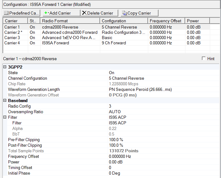
This table enables you to view the key parameters for each carrier in the waveform. You can also add or delete carriers using the buttons above the table (see descriptions below). Double-clicking a carrier row activates the setup tables for that carrier. You can use a maximum of 25 carriers in the waveforms.
Default: Varies by Radio Format
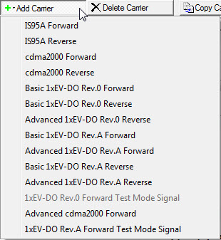
Opens a drop-down menu
with the predefined carrier configuration selections. Double-clicking
a predefined carrier configuration in the window replaces the current
carrier configurations in the Carrier Configuration Summary Table.
Opens a drop-down menu
which allows you to add a carrier to the current configuration. The new
carrier is added immediately above the currently highlighted carrier in
the Carrier Configuration Summary Table.
Deletes the highlighted carriers in the Carrier Configuration Summary Table.
Copies the highlighted carrier and appends the copy to the bottom of the carrier list.
Selections: On, Off
Default: On
Sets the state of the selected carrier to either on or off. The ![]() icon at the right edge of the entry box displays
a drop-down list with all available selections.
icon at the right edge of the entry box displays
a drop-down list with all available selections.
Selections: Varies by
radio format
Default: Varies by radio format
Sets the predefined channel configuration of the selected carrier. The
![]() icon at the right edge of the entry box displays
a drop-down list with all available selections. The configuration can
also be set by selecting the
icon at the right edge of the entry box displays
a drop-down list with all available selections. The configuration can
also be set by selecting the ![]() button in each of
the Channel Setup
panes.
button in each of
the Channel Setup
panes.
Range: 0 to 30
Default: 2
Sets the number of repetitions this frame is used in the sequence.
Range: 2 to 127
Default: 7
Sets the medium access control (MAC) index for the forward link traffic channel.
Selections: True or False
Default: True
Select True, if you want to use the bits entered in the RPC Data field. Select False, if you want to set the RPC data in the TimeSlots node.
Default: 01
Sets RPC data used in MAC channel.
Range: 1 to 100
Default: 1
Note: 1 Super frame is 240 ms length
Enter a number of frames for the selected carrier.
The number of frames in a multi-carrier waveform is determined by the carrier with the largest number of frames. In carriers in the waveform with fewer frames, the frames are repeated until the number of frames matches that in the longest carrier. For example, for two carriers A and B in the same waveform, if A has 10 frames and B has 3 frames, B is repeated 3 times completely, then one more frame from B is used before both A and B start again.
Selections: On, Off
Default: On
Expands the generated sequence to one waveform file. On means it will generate one waveform instead of a sequnece containing 2 waveforms.
Displays the length of the waveform.
Displays the chip rate setting of the selected carrier.
|
Selections: |
|
|
|
IS95A and cdma2000 Carriers: PN Sequence Period (26.666…ms), 1 PCG (1.25 ms), 2 PCG's (2.5 ms), 3 PCG's (3.75 ms), 4 PCG's (5 ms), 5 PCG's ( 6.25 ms), 6 PCG'g (7.5 ms), 7 PCG's (8.75 ms), 8 PCG's (10 ms), 9 PCG's (11.25 ms), 10 PCG's (12.5 ms), 11 PCG's (13.75 ms), 12 PCG's (15 ms), 13 PCG's (16.25 ms), 14 PCG's (17.5 ms), 15 PCG's (18.75 ms), 16 PCG's (20 ms) |
|
|
Basic 1xEV-DO Carriers except Basic 1xEV-DO Rev.A Reverse Carrier: Physical Layer Packet (26.666…ms), 1 Slot (1.666…ms), 2 Slots (3.333…ms), 3 Slots (5 ms), 4 Slots (6.66…ms), 5 Slots (8.333…ms), 6 Slots (10 ms), 7 Slots (11.666…ms), 8 Slots (13.33…ms), 9 Slots (15 ms), 10 Slots (16.666…ms), 11 Slots (18.333…ms), 12 Slots (20 ms), 13 Slots, (21.666…ms), 14 Slots (23.333…ms), 15 Slots (25 ms) |
|
|
Basic 1xEV-DO Rev.A Reverse Carrier: Auto, 1 Slot (1.666…ms), 2 Slots (3.333…ms), 3 Slots (5 ms), 4 Slots (6.66…ms), 5 Slots (8.333…ms), 6 Slots (10 ms), 7 Slots (11.666…ms), 8 Slots (13.33…ms), 9 Slots (15 ms), 10 Slots (16.666…ms), 11 Slots (18.333…ms), 12 Slots (20 ms), 13 Slots, (21.666…ms), 14 Slots (23.333…ms), 15 Slots (25 ms) |
|
Default: |
|
|
|
IS95A and cdma2000 Carriers: PN Sequence Period (26.666…ms) |
|
|
Basic 1xEV-DO Carriers except Basic 1xEV-DO Rev.A Reverse Carrier: Physical Layer Packet (26.666…ms) |
|
|
Basic 1xEV-DO Rev.A Reverse Carrier: Auto |
Double-click or use the drop-down menu to select the waveform generation length.
For the Basic 1xEV-DO Rev.A Reverse carrier, when Auto is the selection, the carrier length is determined by the Data Packet Transmission Repetition value:
For a value of 3, the Waveform Generation Length is 240 ms.
For a value other than 3, the Waveform Generation Length is 80 ms.
A waveform offset is available using the Waveform Generation Offset parameter when one of the following conditions apply:
For IS95A and cdma2000 carrriers, when less than a PN Sequence Period is selected.
For Basic 1xEV-DO Carriers except Basic 1xEV-DO Rev.A Reverse Carrier, when less than one physical layer packet is selected.
For Basic 1xEV-DO Rev.A Reverse carrier, when Auto is not the selection.
This parameter appears in the software's GUI only when Minor Enhancement Update (MEU) Option U02 or greater is valid. Refer to Licenses for more information.
Range: 0–15 PCG/Slot (15 is the waveform generation length)
Default: 0.0 ms
Coupling:
This setting is grayed out until one of the following conditions is met using the Waveform Generation Length parameter:
For IS95A and cdma2000 carrriers, when less than a PN Sequence Period is selected.
For Basic 1xEV-DO Carriers except Basic 1xEV-DO Rev .A Reverse Carrier, when less than one physical layer packet is selected.
For Basic 1xEV-DO Rev.A Reverse carrier, when Auto is not the selection.
Sets the waveform generation offset, when the waveform generation length selected is less than 16 PCGs/slots. The offset value is clipped so that the offset and the waveform length does not exceed 16 PCGs/slots
This parameter appears in the software's GUI only when Minor Enhancement Update (MEU) Option U02 or greater is valid. Refer to Licenses for more information.
Displays the radio configuration selection of the selected carrier. This cell is displayed in CDMA2000 Reverse only.
Selections: Auto, 1, 2, 4, 8, 16, 32, and 64
Default: Auto
Sets the oversampling ratio of the selected carrier. The ![]() icon at the right edge of the entry box displays
a drop-down list with all available selections.
icon at the right edge of the entry box displays
a drop-down list with all available selections.
Displays the filter type selection and the appropriate filter parameters for the selected carrier.
The filter type and parameters may be changed using the filter entry
when the ![]() icon is displayed. If the
icon is displayed. If the ![]() icon is displayed, click it to expand the Filter
selection area allowing you access to the filter selections and parameters.
icon is displayed, click it to expand the Filter
selection area allowing you access to the filter selections and parameters.
Sets the baseband filter type. The ![]() icon at the right
edge of the entry box displays a drop-down list with all available selections.
icon at the right
edge of the entry box displays a drop-down list with all available selections.
Range: None, Root Nyquist, Nyquist, Rectangle,Gaussian, IS95 STD, IS95 STD EQ, IS95 ACP, IS95 ACP EQ, IS95 EVM EQ
Default: IS95 STD EQ
If the overSampling ratio is set to 1, the filter type is automatically set to None, and the filter types and corresponding filter parameters are not available.
If the oversampling ratio is set to any other value, you can select one of the listed filter types and edit the associated parameters.
Range: Filter factor for Nyquist and Root Nyquist filters
Default: 0.22
Changes the Alpha parameter for Root Nyquist and Nyquist filters. This field is inactive with other filter selections.
Range: Filter factor for Gaussian filter
Default: 0.5
Changes the BbT parameter for a Gaussian filter. This field is inactive with other filter selections.
Range: 10% – 100%
Default: 100%
Sets the circular clipping percentage for each carrier prior to finite impulse response (FIR) filtering of the I and Q data. Clipping limits power peaks in waveforms by clipping the I and Q data to a selected percentage of its highest peak. Circular clipping is defined as clipping the composite I/Q data (I and Q data are equally clipped). For more information, see Understanding Waveform Clipping. A level of 100.0% equates to no clipping.
Range: 10% – 100%
Default: 100%
Sets the circular clipping percentage for each carrier after finite impulse response (FIR) filtering of the I and Q data. Clipping limits power peaks in waveforms by clipping the I and Q data to a selected percentage of its highest peak. Circular clipping is defined as clipping the composite I/Q data (I and Q data are equally clipped). For more information, see Understanding Waveform Clipping. A level of 100.0% equates to no clipping.
Displays the length of the waveform in sample points. You cannot edit
this cell. Total Sample Points is directly related to the Oversampling Ratio value selected. The higher
the oversampling ratio, the larger the number of waveform sample points.
Oversampling Ratio–Total
Sample Points Details…
Range: –37.5 to 37.5 MHz
Default: 0.000000 Hz
Sets the frequency offset for the carrier relative to the signal generator's frequency setting. This parameter is coupled with Oversampling Ratio.
Range: –40 to 0 dB
Default: 0.00 dB
Sets the carrier's power relative to the signal generator's amplitude setting.
Range: 0 – 359 Deg
Default: 0 Deg
Sets the initial phase (in degrees) of the carrier.
Range: 0 to 511
Default: 0
Sets the Pseudo Noise (PN) offset for the selected channel.