Use the settings under ![]() 1-seg n
node
to configure parameters for each segment when the super segment type is
set to Type B.
1-seg n
node
to configure parameters for each segment when the super segment type is
set to Type B.
Seg No# shows the segment index in the current type B super segment.
Code Rate shows the code rate of the convolutional coder in the segment.
Modulation Type shows the modulation format used in the segment.
|
System Descriptor (TMCC B20-B21) Indicator of Transmission-parameter Switching (TMCC B22-B25) Next Information (TMCC B67-B106) |
|
This cell displays the super segment index.
This cell displays the center frequency of the super segment.
This cell displays the number of segments in the super segment.
Range: 0 to 32
Set the start segment number of the current super segment.
Range: 0 to 32
This cell displays end segment number of the current super segment.
In this setting table, the value of the end segment number is the same to the start segment number.
Choice: ON | OFF
Default: ON
Double-click or use the drop-down menu to enable or disable the RS encoder. If the RS encoder is off, the payload is treated as the output of a RS encoder and fed into the energy dispersal directly.
This cell displays the settings of hierarchical layer A of the current super segment. There is only one layer in the 1-segment form.
This cell displays the number of segments assigned to this layer, which is 1 in the 1-segment form.
Choice: 1/2 | 2/3 | 3/4 | 5/6 | 7/8
Default: 2/3
Double-click or use the drop-down menu to select the code rate of convolutional coder in this layer.
Choice: DQPSK | QPSK | 16QAM | 64QAM
Default: QPSK
Double-click or use the drop-down menu to select the modulation type in this layer.
Choice:
For Mode 1: 0 | 4 | 8 |16
For Mode 2: 0 | 2 | 4 | 8
For Mode 3: 0 | 1 | 2 | 4
Default: 4
Double-click or use the drop-down menu to select the length of time interleaving in this layer.
This cell displays the maximum bit rate in this layer.
Sets the user defined pattern. This cell is visible only when the Data Source Type is set to Test Pattern.
Click the right button
to open ![]() Data Pattern Selection
dialog and select test pattern to use.
Data Pattern Selection
dialog and select test pattern to use.
Choice: w0 | w1
Default: w0
An synchronizing signal is designed to establish synchronism between transmission and reception of a TMCC signal and an OFDM frame.
Double-click or use the drop-down menu to select the synchronizing signal used in TMCC.
|
B1 -B16 |
Synchronizing Signal (w0 = 0011010111101110, w1 = 1100101000010001) |
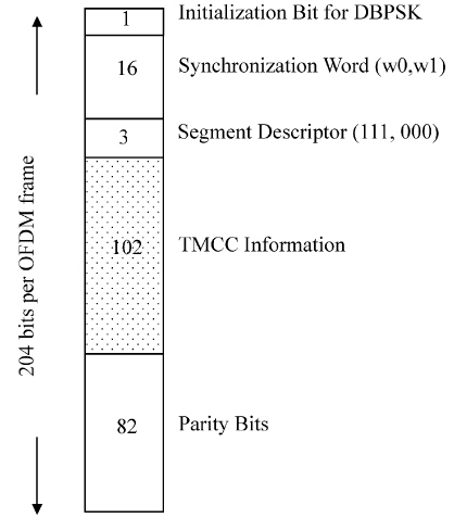
Figure 1 Initial Synchronizing Signal in OFDM frame
This cell displays the broadcasting type. For 1-segment form, it is always ISDB-Tsb.
ISDB-T: Digital terrestrial television broadcasting system, in which transmission bands consist of 13 OFDM segments;
ISDB-Tsb: Digital terrestrial television broadcasting system, in which transmission bands consist of one OFDM segments.
Set the sub-channel number for the current segment. The initial value of the PRBS-generating circuit for the current segment is decided by the sub-channel number.
This cell displays system descriptor bits in TMCC from B20 to B21."00" stands for ISDB-T system. "01" stands for ISDB-Tsb system.
Range: 0000 to 1111
Default: 1111
Set the indicator of transmission-parameter switching specified in TMCC B22 to B25.
Choice: ON | OFF
Default: OFF
Double-click or use the drop-down menu to set the start flag for emergency-alarm broadcasting which is specified in TMCC B26.
Set the next information, which includes the transmission parameters following switching. If the next information input is null, it will be the same as the current information.
Range: 00 to 11
Default: 00
Set phase correction bits in TMCC from B107 to B109.
Range: 000000000000 to 111111111111
Default: 000000000000
Set reserved bits in TMCC from B110 to B121.
Choice: Data Pattern Editor | AC Builder Tool
Default: Data Pattern Editor
Double-click or use the drop-down menu to select the generation method of AC bits.
Click  on the right side of the cell to set the
AC information.
on the right side of the cell to set the
AC information.
If the AC Setup is set to
Data Pattern Editor, a ![]() Data Pattern Selection
dialog will be opened up to set the test pattern to be used as AC bits.
Data Pattern Selection
dialog will be opened up to set the test pattern to be used as AC bits.
If the AC Setup is set to
AC Builder Tool, an ![]() ISDB-T AC Builder
dialog will pop up. See the topic "Using the AC Builder Tool to generate the AC
signal" for the detailed steps of using ISDB-T AC builder to
configure the earthquake alarm information sent in the AC bits.
ISDB-T AC Builder
dialog will pop up. See the topic "Using the AC Builder Tool to generate the AC
signal" for the detailed steps of using ISDB-T AC builder to
configure the earthquake alarm information sent in the AC bits.
AC (Auxiliary Channel) is used to transmit additional information. AC1 is available in an equal number in all segments, while AC2 is available only in different modulated segments.
The useful bit rate. The bit rate can be transmitted by current encoding, modulation, and framing configurations.
The supported file size for the current settings.
Choice: ON | OFF
Default: OFF
Double-click or use the drop-down menu to enable or disable the Re-Multiplexer.
The TS payload settings.
Choice:
Normal: Test Pattern | Demo File | TS File | TS File Wizard
When RS Encoder is off: Test Pattern | TS File
For one-seg ISDB-T: Test Pattern | TS File | TS File Wizard
Default: Test Pattern
Double-click or use the drop-down menu to select which type to be used as the data source.
If TS File" is selected, "File Name" is required;
If "TS File Wizard" is selected, "File Wizard" is available. Following the steps in "Import the transport stream file" to customize your TS file.
To learn more about the different Data Source Types, refer to the topic "Data Source Type".
Choice: True | False
Default: False
Double-click or use the drop-down menu to determine whether a SYNC byte (0x47) should be inserted into the test pattern.
Click on the right side of the cell to load your
desired TS file.
This cell is visible only when the Data Source Type is set to TS File.
Choice: On | Off
Default: On
Double-click or use the drop down menu to select whether or not to use auto-stuffing to agree with the transport bit rate.
This cell is visible only when the Data Source Type is set to TS File.
Choice: On | Off
Default: On
Double-click or use the drop-down menu to determine whether or not to modify the TS file to make it suitable for loop play.
This cell is visible only when the Data Source Type is set to TS File.
This cell displays the size of opened file.
This cell displays the bit rate of the opened file.
This cell displays the time that file can be played.