Frequency Offset Mode


Frequency Offset Mode (FOM) provides the capability to have the VNA Sources tune to frequencies that are different (offset) from the VNA Receivers.

 This topic discusses the VNA settings that are relevant to making these types of measurements. See Frequency Converting Device Measurements for more information on making specific device measurements.

Note: (M980xA, P50xxA/B) This function is available when S9x082A/B, S9x083A/B or S9x090A/B is installed.

Other Frequency Offset topics

How to make Frequency Offset settings

Using Hardkey/SoftTab/Softkey

  1. Press Sweep > Source Control  > Frequency Offset....


Frequency Offset dialog box help

Second Source or Multi-Module/Unit Configuration

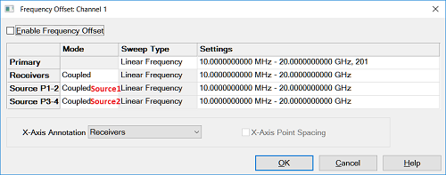
When the unit has the second source capability or multi module/unit configuration in PXI/USB VNA, the different frequency settings can be set for each source.

The following dialog shows an example of three module configuration of  six, four and two port PXI VNAs. Each module can has different frequency setting at the Un-Coupled mode.

The following are major changes to FOM:

  • Stimulus and Response are now called Sources and Receivers.

  • Sources and Receivers settings can be made in two ways:

    1. By Coupling to the Primary (Channel) settings. This is the only method used in previous releases.

    2. By Uncoupling and setting Sources and Receivers values independently. This is the new, simplified method.

  • External sources appear here and can be controlled from this dialog. Learn more.

Note:  Turn the each source  ON using the Power and Attenuators dialog. This (Frequency Offset) is the only dialog for controlling the frequency of each source.

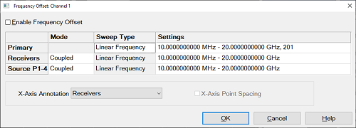
Frequency Offset (ON/OFF)  Enables Frequency Offset Mode on ALL measurements that are present in the active channel.

When FOM is NOT enabled, all frequencies are the same as the active channel.

Tip: First make other settings on this dialog box, then click Frequency Offset ON.

Primary  The current Active Channel settings. When a Source or Receiver is coupled to the Primary settings, its Sweep Type is the same as that of the Primary.  The frequency settings of the coupled range are mathematically derived from the Primary settings using the Multiplier, Divisor, and Offset values. With this approach, only the Primary settings need to be changed in order to affect change in the coupled Sources and Receivers. Changes to the Primary channel settings occur when Frequency Offset is checked ON.  See example using Primary and Coupled setting.

Tip: Primary settings are ONLY used when Sources and Receivers are Coupled. It is often easier to Uncouple, then set Sources and Receivers independently.

Source and Source2 if available. Learn more about Internal Second Source.

Receivers  All receivers that are used in the channel, including Reference receivers, are tuned to the specified frequency settings.

Mode

Coupled  Source and Receiver settings are mathematically derived from the Primary settings using Multiplier, Divisor, and Offset values. Learn more.

Uncoupled  Source and Receiver settings are entered independently, without reference to Primary settings. When Uncoupled, Source and Receiver Ranges can use separate sweep types.

Sweep Type  Click to change the type of sweep for each range. Only available for Primary and Uncoupled Sources and Receivers.

Unsupported Sweep Type combinations

  • Power Sweep and Segment Sweep can NOT be used together.

  • Uncoupled Log Sweep yields invalid data whenever the sources are offset from the receivers.

  • Coupled Log Sweep is allowed only for the following two conditions:

    1. The offset = 0, the multiplier = 1, and the divisor = 1.

    2. The multiplier = 0

Settings  To change settings, click IN the appropriate Settings cell, then click Edit.

X-Axis Annotation  Select the settings to be displayed on the X-Axis:

X-Axis Point Spacing  Only available when a Segment Sweep Type is selected as the X-Axis display. Learn more.

Note:  When Frequency Offset is enabled, ALL receivers on the channel, including the reference receivers, tune to the new offset frequencies, Therefore the source and reference receiver will be at different frequencies. Therefore, FOM measurements that include a reference receiver, which includes all S-parameters, display invalid data.

To measure and display measurements at both the source and receiver frequencies, you must use two channels. Use Equation Editor to calculate the conversion loss. See a calibrated FOM conversion loss example.

Learn how to calibrate frequency offset measurements.


Coupled settings dialog box help

Coupled Formulas:

Range Start = [Primary Start x (Multiplier / Divisor)] + Offset

Range Stop = [Primary Stop x (Multiplier / Divisor)] + Offset

Where:

Offset  Specifies an absolute offset frequency in Hz. For mixer measurements, this would be the LO frequency. Range is +/- 1000 GHz. Offsets can be positive or negative.

Multiplier  Specifies (along with the divisor) the value to multiply by the stimulus. Range is +/- 1000.

  • Negative multipliers cause the stimulus to sweep in decreasing direction. For downconverter mixer measurements, this would be for setups requiring the Input frequency to be less than LO frequency. See an example.

  • 0 (zero) as the multiplier nulls the Primary setting. Then the Offset value adds to zero.

Divisor  Specifies (along with the multiplier) the value to multiply the stimulus. Range is 1 to 1000.


Primary and Uncoupled settings dialog box help

This dialog will vary depending on the sweep type:

Linear and Log frequency

Uncoupled Log sweep yields invalid data whenever the sources are offset from the receivers.

Select Start/Stop or Center/Span

Frequency  Enter values

Points  (Primary only) Enter number of data points for the sweep.

Power

CW Freq  Enter frequency in Hz.

Points  (Primary only) Enter number of data points for the power sweep.

CW Time

CW Freq  Enter frequency in Hz.

Sweep Time  Enter time to complete one sweep. Enter 0 for the fastest sweep.

Segment Sweep  Edits are made exactly like the standard segment table.

For Advanced Users: Uncoupled Segment Sweep offers great flexibility in configuring measurements. In segment sweep mode:

  • The OK button is NOT available until the total number of data points for all segments matches the number of Primary data points.

  • Independent IF Bandwidth and Independent Sweep Time are available ONLY on the Primary (channel) and the Uncoupled Receivers - NOT Sources.

  • Independent Power is available ONLY on the Primary (channel) and the Uncoupled Sources - NOT Receivers.

Setup Examples

Although the Frequency Offset settings can be used with many types of devices, these examples include mixer terminology.

1.

Fixed LO - Upconverter

  • Swept Stimulus (Mixer Input): 1000 MHz - 1200 MHz

  • Fixed LO: 1500

  • Swept Response (Mixer Output): 2500 MHz to 2700 MHz

Make the following settings on the FOM dialog

Source: Uncoupled

Sweep Type: Linear

Click Settings, then Edit. In the Source dialog:

Start Frequency = 1000 MHz

Stop Frequency = 1200 MHz

Receiver: Uncoupled

Sweep Type: Linear

Click Settings, then Edit. In the Receiver dialog:

Start Frequency = 2500 MHz

Stop Frequency = 2700 MHz

LO Settings

Set external source to CW - 1500 MHz.

Source2: Uncoupled (Only with Second VNA Internal Source)

Sweep Type: CW Time

Click Settings, then Edit. In the Source2 dialog:

CW Frequency = 1500 MHz

2.

Fixed LO - Downconverter (Input < LO)

  • Swept INCREASING Stimulus (Mixer Input): 1000 MHz to 1100 MHz

  • Fixed LO: 2500 MHz

  • Swept DECREASING Response (Mixer Output) 1500 MHz to 1400 MHz

Make the following settings on the FOM dialog

Primary: Not used

Source (Input): Uncoupled

Sweep Type: Linear

Click Settings, then Edit. In the Source dialog:

Start Frequency = 1000 MHz

Stop Frequency = 1100 MHz

Receiver (Output): Coupled

Sweep Type: Linear

Click Settings, then Edit. In the Receiver dialog:

Offset: 2500 MHz

Multiplier: -1 (Minus one)

LO Settings

  • If using external source, set  to CW: 2500 MHz.

  • If using Source2: Set to Uncoupled, then:

Sweep Type: CW Time

Click Settings, then Edit. In the Source2 dialog:

CW Frequency = 2500 MHz

See a calibrated FOM conversion loss example.

3.

Swept LO - Fixed Output - Upconverter

Swept External LO measurements in Frequency Offset Mode can be very difficult. The external LO source must be synchronized with the swept output or input (as in this case). See Synchronizing and External Source Control to see how this is done. The Frequency Converter Application Opt S9x083A/B performs makes these measurements easily.

Note: (M980xA/P50xxA) The state for an external source in Power and Attenuator dialog  must be set at ON after enabling FOM in Frequency Offset dialog. Auto state does not work.

  • Swept Stimulus (Mixer Input): 1000 MHz to 1100 MHz

  • Swept LO: 1500 MHz to 1400 MHz

  • Fixed Response (Mixer Output): 2500 MHz

Make the following settings on the FOM dialog

Source: Uncoupled

Sweep Type: Linear

Click Settings, then Edit. In the Source dialog:

Start Frequency = 1000 MHz

Stop Frequency = 1100 MHz

Receiver: Uncoupled

Sweep Type: CW Time

Click Settings, then Edit. In the Receiver dialog:

CW Frequency = 2500 MHz

LO Settings

  • If using external source, set to sweep from 1500 - 1400 MHz.

  • If using Source2 (Second Internal Source):set to Uncoupled, then:

Sweep Type: Linear

Click Settings, then Edit. In the Source2 dialog:

Start Frequency = 1500 MHz

Stop Frequency = 1400 MHz

4.

Power Sweep for Mixers

To measure the gain compression of a mixer, the input power to the mixer is swept. The input and output frequencies are fixed but offset from one another.

This is a good use of Coupled settings because the same compression test can be performed at several different frequencies. With coupled Source and Receiver ranges, the Primary (channel) frequency can be easily changed from the front panel. The coupled source and receiver frequencies will update accordingly.

  • Swept Input Power: -10 dBm to 0 dBm

  • Fixed Input Frequency: 1500 MHz

  • Fixed LO: 500 MHz

  • Fixed Output: 2000 MHz

Make the following settings on the FOM dialog

Primary:

Sweep Type: Power Sweep

Click Settings, then Edit. In the Primary dialog:

CW Frequency = 1500 MHz

Source: Coupled

Default settings make CW Frequency: 1500 MHz (same as Primary)

Receiver: Coupled

Default settings make Sweep Type: CW Time

Click Settings, then Edit. In the Receiver dialog:

Offset  = 500 MHz

LO Settings

  • If using external source, set  to CW: 500 MHz.

  • If using Source2 (Internal Second Source),:set to Coupled, then:

Sweep Type: Power Sweep

Click Settings, then Edit. In the Source2 dialog:

CW Frequency = 500 MHz