Option M937xA-009, P937xA-S97080 and S97082A, and M9485A-009 allows Scalar Mixer Converter (SMC) measurements on a maximum of four ports.
Note: With the FOM measurement on, the receiver gain is fixed to “Low” although “Auto” is shown in the dialog box. Set "High" manually if the high gain is required.
In this topic:
For a detailed understanding of FCA, see our Mixer Measurements App Notes.
M937xA Option 009 or P937xA Option S97080A/S97082A includes Scalar Mixer Converter (SMC) measurements. M9485A provides which includes Scalar Mixer (SMC) and Vector Mixer (VMC) Measurements.
Note: The VMC of the M9485A is provided by macro.
|
|
Scalar Mixer Calibration |
|
|
Overview |
Provides highest Scalar accuracy for measurements of conversion loss/gain. Combines SOLT and power-meter calibration. |
|
|
Measurements Offered |
Both forward and reverse directions. DUT can be connected to any VNA ports. |
|
|
Equipment Required |
Power meter and sensor |
|
|
Common equipment for SMC
|
||
See Comparison of Mixer Characterization using New Vector Characterization Techniques.
The following VNA features are NOT available with FCA:
Analog Sweep (Stepped sweep mode only)
Log frequency sweeps
ECal User Characterization (can NOT be created in FCA channel)
Some Fixturing Features
The following is an overview of how to make an FCA measurement:
CREATE an SMC Measurement.
SETUP the measurements.
CALIBRATE your measurement.
Press Setup > Main > Meas Class....
Select SMC, then either:
OK delete the existing measurement, or
New Channel to create the measurement in a new channel.
See SMC measurements to learn about the parameters that are offered in each.
How to make SMC settings |
|
Using Hardkey/SoftTab/Softkey |
Using a mouse |
|
|
Configuring the SMC Setup dialog can be challenging at first. RED messages like this one appear at the bottom of the Setup dialog to notify you of an invalid setup.
![]()
At least one range (Input, LO, or Output) MUST be Fixed.
The following are the Valid Mixer Configurations:
|
Sweep Type |
Input |
LO |
Output |
|
Linear |
Swept |
Swept |
Fixed |
|
Swept |
Fixed |
Swept |
|
|
Fixed |
Swept |
Swept |
|
|
CW Time Power |
Fixed |
Fixed |
Fixed |
TipsAlthough you will soon become comfortable navigating these tabs, at first it may be best to complete the dialog in the following order:
|
Sweep TypeLinear Sweep frequency. Measurements are displayed on a standard grid with ten equal horizontal divisions. Learn how to select the range to display on the X-Axis. CW Time All ranges are set to a Fixed (CW) frequency, and the data is displayed versus time. Segment Sweep Sweep user-defined segments. Learn more. Power Sweep Input or LO power.
X-axis Point Spacing (Available only with Segment Sweep) - Learn about this feature Number of Points Learn about this feature. IF Bandwidth Learn about this feature. Phase Reference Point (SMC ONLY) Learn about this feature.
|
|
Note: Set LO Power on the Mixer (LO) Power tab. Configures Input and Output power settings for an FCA measurement. Use the Mixer Power tab to set LO power. Power ON (All channels) Check to turn RF Power ON or clear to turn power OFF for all channels. Port Powers Coupled Check to set the same power level at the DUT Input and Output ports. The LO power is NOT coupled. Clear to set power levels independently for each test port. Uncouple power, for example, to apply more power in the reverse direction than in the forward direction Learn more about Setting Independent Port Power DUT Input / Output PortSelect the VNA port that is connected to the DUT Input and Output. For VMC, the DUT input must always be connected to VNA port 1 because of the need for a reference mixer on port 1. Power Level Set the power level to the DUT Input port. To set power at the Output port, clear the Port Powers Coupled checkbox. Source Attenuator Auto Check to automatically select the correct attenuation to achieve the specified input power. Clear, then select attenuator setting that is used achieve the specified Power Level. Learn more about Source Attenuation. All VNA channels in continuous sweep must have the same attenuation value. Learn more. Receiver Attenuator Specifies the receiver attenuator setting for the DUT port. Source Leveling Choose from: Internal (normal operation), Open Loop (used only for Wideband Pulse measurements), or Receiver - R1 for Receiver Leveling. DUT Input and Output Port Power SweepAvailable when Power (sweep) is selected on the Sweep tab. Input Start and Stop Power To set Start and Stop power at the Output port, clear the Port Powers Coupled checkbox. Note: If your DUT requires more input power than this setting allows below 3.2 GHz, use the PNA-X Hi-power mode, available from the RF Path Configuration dialog. The disadvantage to this is higher harmonic content. Power Points Number of power points to measure. Power Step (Size) Calculated value from current Start, Stop, and Points settings. This setting can NOT be changed directly.
|
The following tabs are shared with all Mixer / Converter Applications:
|
|
|
|
|
|
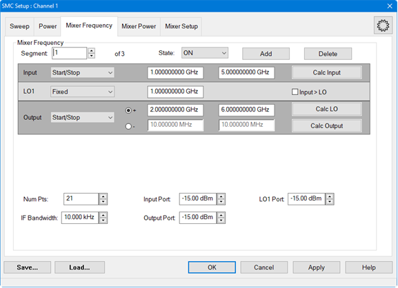
The following settings appear on the Mixer Frequency tab when Segment Sweep is selected on the Sweep tab.
|
Mixer Frequency tab - Segment Sweep - SMC dialog box help |
|
How to configure a segment using the GUI:
How to add multiple segments using the GUI and Excel *.csv file:Start with the GUI to set up mixer settings and to create the first segment then save it as a *.csv file. The *.csv file will then be opened in Excel and the additional segments will be entered. Learn more.
|
In general, when a Cal Set covers a wider frequency range than the channel, the VNA will offer to interpolate the Cal Set when it is applied. Learn more. However, with FCA measurements the LO frequency range may also be considered.
SMC measurements ALWAYS IGNORE the LO frequency range. Therefore, if the Input and Output frequency ranges of the measurements are within those of the Cal Set, then the Cal Set is interpolated if necessary and applied. For example, this would allow you to perform ONE SMC calibration with Input range = the VNA frequency span, LO at 0 Hz, and Output range + the VNA frequency span. This Cal Set could be applied to ALL SMC measurements. Learn more about applying SMC Cal Sets.
These same general concepts apply to segment sweeps. However, if ALL applicable frequency ranges (SMC: Input and Output) are NOT within those ranges of the measurement for ONE segment, then the Cal Set is NOT applied for ANY segment.
Click Sweep > Main > X-Axis Type, then select the desired type.
When Sweep Type = Linear, you can choose to show the frequency range of any of the swept parameters on the X-axis.
For example, the following image shows an SMC Fixed Output response with the Input frequency range on the X-axis:
Output: 100 MHz (data trace)
Input: 2 GHz to 23 GHz (X-axis)
LO: 1.9 GHz to 22.9 GHz (not shown)
Marker annotation shows Output power at Input frequency.
You can save your FCA measurement data in several standard formats.
Click Save Recall > Save Other > Save Data....
The following shows how CSV and SNP files are saved.
When you select Mixer Trace Data, the FCA data is saved to a CSV file in the following format:
#MIXER TRACE FILE,A.01.00
SegIndex, InputFreq, OutputFreq, LO1Freq, InputPower, LO1Power, SC21 Mag (dB), SC21 Phase (Deg)
Each record contains 1 stimulus value and 4 parameters (total of 9 values) as follows:
Stim Real(p1) Imag(p1) Real(p2) Imag(p2) Real(p3) Imag(p3) Real(p4) Imag(p4)
where pX is the parameter depending on measurement type:
|
Measurement Type |
p1 |
p2 |
p3 |
p4 |
|
Scalar |
S11 |
SC21 (FWD) |
SC12 (REV) |
S22 |
If correction is OFF, data is only saved for the active parameter. Zeros are saved for all other parameters.
If correction is ON, data is saved for all of the parameters.
All files contain the following Header Information: Brackets [ ] contain parameters.
!Keysight [Instrument Model Number]: [version]
!Mixer S2P File: [Mixer Measurement Type]
!Parameters: [Parameter List]
!Calibration State: [On/Off]
!# Begin Mixer Setup
![Mixer Setup parameters listed here]
![Mixer Parameter 1]
.
.
![Mixer Parameter n]
!# End Mixer Setup
# [S2P data here]