|
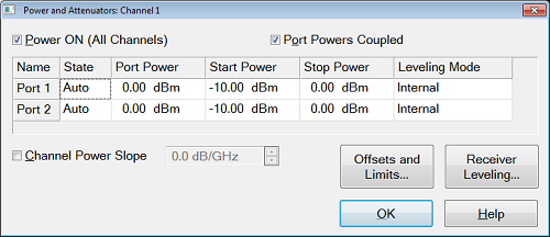
Defines and controls the source power and attenuation for the active channel.
Note: External sources can be controlled from this dialog. Learn more.
Power On (All Channels) Check to enable source power for all channels (same function as RF Power). Only turns power ON if channel power setting is ON or Auto.
Port Powers Coupled
-
Coupled (checked) The power levels are the same at each test port. Set power at any test port and all test ports change to the same power level.
-
Uncoupled (cleared) The power levels are set independently for each test port. Uncouple power, for example, if you want to measure the gain and reverse-isolation of a high-gain amplifier. The power required for the input port of the amplifier is much lower than the power required for the output port. A power sweep can also be performed with uncoupled power. Learn more about Setting Independent Port Power
Name Lists the analyzer test ports.
State
Port Power Sets the power level at the output of the source.
Start / Stop Power Available ONLY when sweep type is set to Power Sweep. Set the start and stop power values of a power sweep. Learn how to set Power Sweep.
-
You can specify whether to maintain source power at either the start power or stop power level at the end of a power sweep. Learn more.
-
A power sweep can be performed with uncoupled power. Different power ranges can be swept in the forward and reverse directions.
Leveling Mode
-
Internal - (Except M9485A) Source correction factors are used to provide a flat output power within specifications. NO internal circuitry is used to level the output power (No ALC).
- (M9485A) ALC leveling.
-
Open Loop - No ALC. The source power level accuracy is very compromised. (M9485A only)
-
Receiver-Rn - Receiver Leveling (n = port number). Select a receiver to use for leveling the source. Available for internal ports only. Learn more.
Note: Receiver Leveling can be used with EITHER Internal ALC or Open Loop. See Enable ALC Hardware on the Receiver Leveling dialog.
Channel Power Slope
Helps compensate for cable and test fixture power losses at increased frequency. With power slope enabled, the port output power increases (enter positive value) or decreases (enter negative value) as the sweep frequency increases.
Slope Select to set the power slope. Clear to set power slope OFF.
Power slope is computed and applied from 0 GHz – not from the measurement start frequency.
For example, with the following measurement settings:
The power into the DUT from 10 GHz to 20 GHz is 10 dBm sloping to 20 dBm
Offset and Limits Launches the Power Offset and Limits dialog.
Receiver Leveling Launches the Receiver Leveling dialog.
Receiver Attenuator Launches the Receiver Attenuator dialog. (M9485A with M9377A only)
Source Unleveled
When the power level that is required at a test port is higher than can be supplied, a Source Unleveled error message appears on the screen and the letters LVL appear on the status bar.
To resolve an unleveled condition, change either the Test Port Power or Attenuator setting.
Important Note: The available power range can also be adjusted AUTOMATICALLY by a Source Power Calibration, Guided Power Cal, or Power Compensation. If you are NOT seeing the range that you expect, or the correct power level at your DUT, view the Power Offset column in the Power Limits and Offsets dialog.
Setting Independent Port Power
You can uncouple port power and specify different power levels at each test port. There are a few things to consider when setting independent port powers.
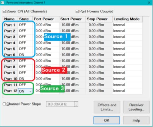
Setting Port Power On/Off for the Second source and Multi Module/Unit configuration
When the unit has the second source capability or multi module/unit configuration in PXI/USB VNA, Source power ALWAYS ON can be applied for each source group.
The following dialog shows an example of three module configuration of six, four and two port PXI VNAs. In this case, there are three independent source group, port 1to 6, 7 to 10 and 11 to 12. You can set one port in each group at ON state.
|
Receiver Attenuators dialog box help
|
|
Receiver Attenuation is used to protect the VNA test port receivers from damage or compression.
CAUTION! You can damage the analyzer receivers if the power levels exceed the maximum values.
|
Power ON and OFF during Save / Recall, User Preset, and Preset
To protect your DUT from being inadvertently powered ON, the following RF Power ON/OFF settings occur:
If power is OFF when an instrument state is saved, then power will always be OFF after the instrument state is recalled.
If power is ON when an instrument state is saved, and the current power setting is OFF, then power will be OFF after the instrument state is recalled.
Instrument Preset sets power ON by default.
This can be changed with a Preference setting so that, if the current power setting is OFF, then power will be OFF after Preset.
Power ON and OFF during Sweep and Retrace
Source power is NOT turned OFF during M937xA/P937xA frequency band crossings or during sweep retrace.
-
Caution: Avoid expensive repairs to your analyzer. Read Electrostatic Discharge Protection.
|