Random electrical noise which shows up in the analyzer receiver chain can reduce measurement accuracy. The following features help reduce trace noise and the noise floor which can lead to better dynamic range and more accurate measurements.
Modulation Distortion Bandwidth Settings (Option S93070xB,A9x070A/B Modulation Distortion only)
See Also
Other topics about Optimizing Measurements
Averaging is a feature that reduces the effects of random noise on a measurement. There are two types of averaging: Point or Sweep.
The Point averaging type computes averaging on each data point before stepping to the next data point. You determine the number of measurements by setting the averaging factor (enabled by clicking the Averaging button). The higher the averaging factor, the greater the amount of noise reduction.
The Sweep averaging type computes averaging on subsequent sweeps until the required number of averaging sweeps are performed.
See also this Keysight support article: HOW TO ACQUIRE DATA USING AVERAGES ON A VNA WITH SCPI EXAMPLE IN PYTHON
Both Averaging and IF Bandwidth can be used for the same benefit of general noise reduction. For minimizing very low noise, Averaging is more effective than reducing IF bandwidth. Generally, Averaging takes slightly longer than IF bandwidth reduction to lower noise, especially if many averages are required. Also, changing the IF bandwidth after calibration results in uncertain accuracy.
How to Set Averaging |
|
|
Using Hardkey/SoftTab/Softkey |
Using a mouse |
|
|
|
Average ON Check to enable Averaging. Average Factor Specifies the number of measurements that are averaged. Range of 1 to 65536 (2^16). Average Type Sweep Each data point is based on the average of the same data point measured over consecutive sweeps. When the number of sweeps = Average Factor, the averaging continues following the Sweep Averaging formula. (Sweep) Restart Begins a new set of measurements that are used for the average. Applies only to Sweep averaging - NOT Point. Point Each data point is measured the number of times specified by the Average Factor, and then averaged, before going to the next data point.
Notes
Sweep Averaging FormulaNewAvg = (NewData/n) + [OldAvg*(n-1/n)] 'where n = average factor From the formula, you can see that data from the first n sweeps continues to be included in the results of subsequent sweeps. Its effect is increasingly smaller but never diminishes to zero. For example, with n = 5, the average of the 5 sweeps is displayed. On the 6th sweep, you see 4/5 the average of the first 5 sweeps plus 1/5 the new sweep. The effects of older data can be eliminated by clicking Restart. Learn more about Averaging (scroll up) |
|
The received signal is converted from its source frequency to a lower intermediate frequency (IF). The bandwidth of the IF bandpass filter is adjustable down to a minimum of 1 Hz. The maximum IF varies depending on the VNA model.
Reducing the IF receiver bandwidth reduces the effect of random noise on a measurement. Each tenfold reduction in IF bandwidth lowers the noise floor by 10 dB. However, narrower IF bandwidths cause longer sweep times.
Channel - IF bandwidth can be set independently for each channel
Segment sweep - IF bandwidth can be set independently for each segment of segment sweep.
Calibration - Changing the IF bandwidth after calibration will cause a 'C-delta' correction level, which means that calibration accuracy is uncertain.
|
Using Hardkey/SoftTab/Softkey |
Using a mouse |
|
or...
|
|
For M938x,
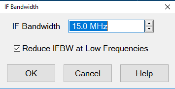
IF Bandwidth Specifies the IF (receiver) bandwidth. The value of IF bandwidth is selected by scrolling through the values available in the IF bandwidth text box. The IF BW is set independently for each channel. Right click on the BW icons on the status bar then select IF Bandwidth... to display the IF Bandwidth dialog: Reduce IF BW at Low Frequencies : This is the same as LF Auto BW. OK Selects the IF BW value shown in the text box. Reduce IF BW at Low Frequencies : This is the same as LF Auto BW. OK Selects the IF BW value shown in the text box.
Learn about IF Bandwidth (scroll up) |
|
Modulation Distortion Bandwidth Settings (Option S9x070xB, S9x070A/B Modulation Distortion only)
|
Using Hardkey/SoftTab/Softkey |
Using a mouse |
|
|
|
Using Hardkey/SoftTab/Softkey |
|
On VNA models with a maximum frequency of 20 GHz and higher, the trace noise becomes worse below about 400 MHz. This is especially obvious between 10 MHz and 45 MHz and also when Time Domain is ON.
This setting:
can be made for each channel.
is ON (checked) by default.
also applies to segment sweep.
When LF Auto BW is ON, the VNA uses a smaller IF Bandwidth than the selected value at low frequencies.
For example:
User set IF Bandwidth : 100 kHz
Receiver Frequency : 180 kHz
180 kHz / 4 = 45 kHz is lower than User set IF bandwitdth 100 kHz. Hence 45 kHz is chosen.
Then, next lower IF Bandwidth is 30 kHz. 30 kHz IF bandwidth is applied for this point.
Use the following calculations to determine the actual IF Bandwidth that is used. If the result is NOT a selectable IF BW, the next higher selectable value is used.
For M9834A/37A models, if LF Auto BW is ON, use smallest value of below:
1. (At least one path is Coupler Path)
User set IF Bandwidth
Closet IF Bandwidth less than or equal to (Receiver Frequency) / 5
Closet IF Bandwidth less than or equal to (User set IF Bandwidth) x Ratio in the table below.
|
M983xA, E5081A |
|||
|
Frequency Upper Limit |
Ratio |
||
|
46,750,000 |
0.005 |
||
|
50,000,000 |
0.0075 |
||
|
62,500,000 |
0.01 |
||
|
78,125,000 |
0.015 |
||
|
142,000,000 |
0.025 |
||
|
175,000,000 |
0.075 |
||
|
296,500,000 |
0.1 |
||
|
470,000,000 |
0.25 |
||
|
810,000,000 |
0.5 |
||
|
1,140,000,000 and above |
1 |
46,750,000 |
0.005 |
|
50,000,000 |
0.0075 |
||
|
62,500,000 |
0.01 |
||
|
78,125,000 |
0.015 |
||
|
142,000,000 |
0.025 |
||
|
175,000,000 |
0.075 |
||
|
296,500,000 |
0.1 |
||
|
470,000,000 |
0.25 |
||
|
810,000,000 |
0.5 |
||
|
1,140,000,000 and above |
1 |
||
2. Paths of all receivers are other than Coupler Path like as DRA, NF Path
User set IF Bandwidth
Closet IF Bandwidth below (Receiver Frequency) / 5
Example: The coupler path is used (The test port is used for measurement), IF BW 30 kHz, frequency point: 1.1 MHz
User Set IF BW: 30 kHz
Closet IF Bandwidth less than or equal to (1.1 MHz) / 5 = 220 kHz: 220 kHz cannot be set as IF BW, Hence 200 kHz is a candidate number for this condition.
Closet IF Bandwidth less than or equal to (30 kHz) x 0.0001 = 3 Hz
Since 3 Hz is the lowest number on three of above, IF BW 3 Hz is used for this points.
Since 3 Hz is the lowest number on three of above, IF BW 3 Hz is used for this points.
Trace smoothing averages a number of adjacent data points to smooth the displayed trace. The number of adjacent data points that get averaged together is also known as the smoothing aperture. You can specify aperture as either the number of data points or the percentage of the x-axis span.
Trace Smoothing reduces the peak-to-peak noise values on broadband measured data. It smooths trace noise and does not increase measurement time significantly.
Because Trace Smoothing follows Format in the data processing map, the formatted data is smoothed. Smoothing is automatically turned off if the format is Polar or Smith Chart.
Learn more about Data Format Types.
Tips:
Start with a high number of display points and reduce until you are confident that the trace is not giving misleading results.
Do not use smoothing for high-resonance devices, or devices with wide trace variations. It may introduce misleading information.
Smoothing is set independently for each trace.
Polar Smoothing will use two types of smoothing math.
| Smooth Math |
Calculation |
|
Mag / Phase |
|
|
Real / Imag |
|
|
Using Hardkey/SoftTab/Softkey |
|
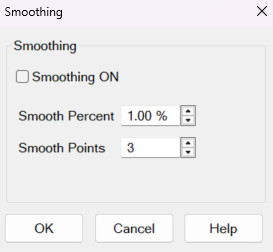
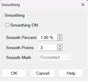
Smoothing ON When checked, applies smoothing to the displayed trace.
Smooth Percent Specify percent of the swept stimulus span to smooth. For example, for a trace that contains 100 data points, and specify a percent of span = 11%, then the number of data points that are averaged is 11.
Smooth Points Specify the number of adjacent data points to average.
Smooth Math For traces formatted as Polar, Smith, Inverted Smith and Complex, there are two selections: "Real / Imag" and "Mag / Phase".
For traces NOT formatted as Polar, Smith, Inverted Smith and Complex, the combo box is grayed out and show "Formatted", indicating that the displayed, formatted data is smoothed.
Learn about Trace Smoothing (scroll up)