Note: The M937xA/P937xA does not support this function.
See Also
Fast, easy, and complete Gain Compression measurements for amplifiers.
Many compression parameters to choose from, including gain, input power at compression, output power at compression, input match, and compression level.
Several compression methods to choose from, including deviation from linear gain, deviation from max gain, back-off, and X/Y, and compression from saturation.
Three acquisition methods to choose from: Power per Freq, Freq per Power, and SMART Sweep
SMARTCal Calibration Wizard to guide you through Full 2-Port or Enhanced Response calibration, plus Source Power calibration.
Compression Analysis allows traditional power sweep view at a selected frequency.
Receiver Leveling provides continuous source power accuracy.
Supports Wideband (NOT Narrowband) Pulse measurements using the new integrated Pulse setup dialogs.
Supports Parallel Gain Compression Measurement for Amplifiers.
Option S9x086A (software option only) must be enabled.
When performing an optional calibration:
ECal module or Calibration Kit
Power meter/sensor
Number of points limited to 100,001 for two-dimensional acquisitions, 50,000 points for SMART Sweep.
Standard CW power sweep is NOT supported in a Gain Compression channel.
Independent IFBW, Power Levels, Shift LO, or Sweep Time in a segment table is NOT supported.
Stepped sweep mode only.
Linear, Log, and Segment frequency sweep modes only.
The following VNA Features are NOT Available in a Gain Compression channel:
Unratioed receiver measurements (A, B, R)
Some Fixturing Features
External Test Set Control
CW Time sweep
Save Auto Formatted Citifile data.
Narrowband Pulse measurements using the Integrated Pulse App
An amplifier has a region of linear gain, where the gain is independent of the input power level. This gain is commonly referred to as small signal gain. As the input power is increased to a level that causes the amplifier to approach saturation, the gain will decrease. The 1 dB gain compression is defined as the input power level that causes amplifier gain to drop 1 dB relative to the linear gain.
You can quickly measure the gain compression using a compression marker on a power sweep trace.
Linear Power Level The specified input power that yields linear gain (also known as 'small-signal gain') in the amplifier.
Reference gain The measured gain that is used as a reference for determining compression level. The Compression Method that is used could cause this value to be different.
Compression level The specified amount of gain reduction from the reference gain.
Target gain The gain at the specified compression level. Although this term does not appear in GCA, it is important to understand when discussing the various compression parameters.
For example, when using Compression from Linear Gain method with the following settings:
Linear gain (measured at Linear Input power) = 10.2 dB
Compression level (specified) = 1 dB
Target gain = 9.2 dB
This is called 'Target' gain because GCA will search for the closest measured gain to 9.2000 dB. It may not measure this gain exactly.
Compression point The operating point at which the measured gain is closest to the Target Gain. All compression parameters report data for this operating point.
One of the most important concepts to remember with GCA is that, each frequency data point represents many measurements using different input power levels.
Some things to notice about how GCA displays compression data:
The X-axis values are ALWAYS frequency. Imagine behind each frequency data point, a traditional power sweep curve with corresponding measurements and calculations to find the specified compression point.
The Y-axis values are always reported at the compression point. The value that is displayed depends on the compression parameter that you choose. The S-parameters that are displayed in a GCA channel are always measured at the linear and reverse power level.
Example: Five of the six GCA compression parameters are displayed in the above image. The missing trace, DeltaGain21 is discussed below.
Markers are placed at 4.549 GHz for all of the parameters.
Tr 3 CompIn21 (Input power at the compression point) shows the marker value to be -5.4117 dBm. This is the power into the DUT that was required to achieve the compression point Notice that this is about the same input power required to achieve the specified compression at ALL frequencies.
Tr 5 CompGain21 (Gain at the compression point) shows the marker value 9..6443 dB . This is the measured gain at the compression point.
To see the gain at a different input power at this frequency, use the Compression Analysis feature.
Press Meas > S-Param > Meas Class....
Select Gain Compression, then either:
OK delete the existing measurement, or
New Channel to create the measurement in a new channel.
There are several Gain Compression parameters, as well as standard S-parameters and ADC parameters, that can be measured in a GCA channel.
How to add GCA Parameters |
|
|
Using Hardkey/SoftTab/Softkey |
Using a mouse |
|
|
For convenience, the standard S-parameters are offered in a GCA channel. S11 and S21 are measured at the specified Linear Input level. S22 and S12 are measured at the specified Reverse power level.
Note: When a DC meter is added, it will be displayed in the New Trace dialog and SMART Sweep Safe Mode dialog (in DC Parameters pull down menu).
|
Parameter |
Description |
When Measured |
|
S11 |
Input Match |
Always |
|
S21 |
Gain |
Always |
|
S22 |
Output Match |
See Reverse |
|
S12 |
Reverse Isolation |
See Reverse |
|
AI1 |
Linear AI1 |
|
|
AI2 |
Linear AI2 |
|
|
Note: The following table assumes: DUT Input = VNA port 1 and DUT Output = VNA port 2. When the Port mapping is different, the parameters in GCA are updated accordingly. For example, with Input = port 2 and Output = port 1, then "CompIn12" would be displayed. |
The raw data for these parameters are always measured.
|
Parameter |
Description |
|
CompIn21 |
Input power at the compression point. |
|
CompOut21 |
Output power at the compression point. |
|
CompGain21 |
Gain at the compression point. |
|
CompS11 |
Input Match at the compression point. |
|
RefS21 |
Linear Gain value used to calculate the compression level. This is calculated differently depending on the compression method. |
|
DeltaGain21 |
CompGain21 MINUS Linear Gain (in Log Mag format). This trace can be used to learn a lot about the DUT compression point. Learn more. |
GCA offers the following methods to find the compression point of an amplifier using GCA:
The Reference Gain is measured using the specified Linear (Input) Power Level. The Target Gain is calculated as the Linear Gain minus the specified Compression Level. For example 8.3 dB - 1 dB = 7.3 dB.
The linear region of an amplifier gain may not be perfectly linear. The highest gain value that is found at each frequency is used as the Reference (S21) Gain. The Target Gain is found in the same way as Compression from Linear Gain.
This method is used to better find the compression point when measuring amplifiers with non-linear gain as shown in the following image:
The Max power out value * is found at each frequency. Then input power is lowered until the output power decreases by the specified 'From Max Pout' value. This is the compression point.^
These two compression methods are very similar.
Both methods specify a difference in input power (X axis) between the linear region and compression point.
For the Y-axis difference:
Backoff method specifies Compression Level which is a difference in Gain.
X/Y method specifies Delta Y which is a difference in Output Power.
GCA searches for these points differently for 2D sweeps and SMART sweep.
The following images show how Backoff and X/Y method is calculated at ONE frequency.
|
|
|
The compression point (yellow circle) is where 10 dB more input power yields 1 dB less gain than at the reference point (blue circle). |
|
|
|
The compression point (yellow circle) is where 10 dB more input power yields only 9 dB more output power than at the reference point (blue circle). |
The GCA offers three modes for data acquisition: Two 2D sweep modes, and SMART sweep.
To see a traditional power sweep at a single frequency, use the Compression Analysis feature. Learn more.
This is the easiest method to understand, and the least efficient for finding the compression point. Both 2D sweep modes work as follows:
All GCA measurements begin by measuring S-parameters at the specified Linear Power level. Reverse parameters are measured ONLY if Full 2-port calibration is applied or if a reverse parameter is displayed. Learn more about Cal choices.
Gain measurements are then made at ALL of the specified frequency and power values. Although these are conceptually 2-Dimensional sweeps, a single sweep is constructed in firmware. See Data Points Limit.
After data has been measured, a search is performed to find the compression point. You can choose to interpolate between the two measured points closest to the target gain. Learn more.
As each sweep is performed, dots are plotted next to the Ch indicator in the lower left corner of the display to indicate progress for the current sweep.
Note: For Backoff and X/Y compression method, GCA does not verify that the specified Start - Stop power range is at least the size of the specified Backoff or X value. The closest compression point is always reported.
Note: SMU Hardware List trigger mode is NOT supported in GCA 2D sweeps.
2D Sweep Power per Frequency - Input power is stepped from Start to Stop at each specified frequency. From the following example you can see that the device is exposed to the highest power level (p3) at the first frequency (f1). This could heat the device early in the measurement and affect compression results.
The following examples show (frequency, power) values for three frequency points and three power points, resulting in a total of 9 measurements:
|
1 |
2 |
3 |
4 |
5 |
6 |
7 |
8 |
9 |
|
f1,p1 |
f1,p2 |
f1,p3 |
f2,p1 |
f2,p2 |
f2,p3 |
f3,p1 |
f3,p2 |
f3,p3 |
2D Sweep Frequency per Power - Frequency is swept from start to stop at each specified power level as follows:
|
1 |
2 |
3 |
4 |
5 |
6 |
7 |
8 |
9 |
|
f1,p1 |
f2,p1 |
f3,p1 |
f1,p2 |
f2,p2 |
f3,p2 |
f1,p3 |
f2,p3 |
f3,p3 |
It is NOT possible to plot ALL of the 2D measurement data on the VNA display. However, it can be saved to a *.csv file and then read into an Excel spreadsheet. The initial S-parameter measurement data is not saved to this file. Learn more.
You can also view on the VNA all power sweep information at a selected frequency using the Compression Analysis feature.
SMART Sweep is usually the fastest and most accurate method to measure Gain Compression. Unlike the 2D acquisition modes which measure all of the specified frequency / power points, SMART Sweep performs a series of power search iterations. At each frequency, an 'intelligent guess' of input power is made to find the compression level that is within tolerance. This guess is further refined with each successive power search iteration sweep.
SMART Sweep continues to iterate until one of the following conditions occur:
ALL data points are within tolerance. When the compression level for a data point achieves the specified tolerance, it continues to be measured and input power changed to improve the measurement within tolerance.
The specified compression level can NOT be achieved for the remaining frequencies that are not in tolerance. Either the Start power is too high or the Stop power is too low.
Maximum iterations have been achieved. If a measured gain is not within the specified tolerance before the specified Max number of Iterations has been reached, then the last power reading is used as the compression point.
The intelligent guess process works differently depending on the compression method. This is important because Backoff and X/Y compression methods subject the DUT to significant changes in input power during an iteration sweep. This can affect the DUT and the measurement results.
Learn all about Backoff and X/Y compression methods.
ALL GCA measurements begin by measuring S-parameters at the specified Linear Power level. Reverse parameters are measured ONLY if Full 2-port calibration is applied or if a reverse parameter is displayed. Learn more about Cal choices.
Backoff and XY Because both compression methods specify the separation between the 'linear" region and the "compressed" region, each iteration requires a single sweep at two dramatically different power levels over the same frequency range. The first half of the sweep measures the DUT at the Backoff or X power level. The second half of the sweep measures the DUT at the compressed power level, specified by the Start and Stop power range. At the beginning of the second half, the power level rises by the Backoff or X value. The specified Settling Time is applied at this point to allow the DUT time to react to this significant change in power level. Safe Sweep does NOT minimize this change in input power. However, Safe Sweep with Backoff and XY methods DOES prevent the DUT from being exposed to too much input power.
Compression From Linear Gain After the reference gain is measured at the linear input power, the next iteration measures the DUT at a higher power level which attempts to push the DUT well into compression. Subsequent sweeps, depending upon the compression level of the DUT, either increases or decreases the power in order to reach the desired compression level. Usually, by the third iteration sweep, a curve-fit algorithm is utilized to precisely find the compression point.
Note: The DUT can be subject to significant changes in power from one iteration sweep to the next. This can be minimized by the use of SAFE Sweep and careful selection of the corresponding settings.
Compression from Max Gain The maximum gain that is found at each frequency is stored and used to calculate the compression point. SMART Sweep does NOT perform extra iterations to search for the maximum possible gain of the amplifier at each frequency.
Compression from Saturation The maximum power out that is found at each frequency is stored and used to calculate the compression point. SMART Sweep does NOT perform extra iterations to search for the maximum possible power out of the amplifier at each frequency.
The following is a general procedure for performing a GCA measurement. The challenge with GCA is configuring a measurement that yields the true compression performance of YOUR DUT. This requires knowledge of the Gain Compression settings and knowledge of the DUT.
See specific dialog boxes below.
Disconnect the DUT if preset or default power levels may damage the VNA or DUT.
Preset the VNA, or configure a suitable User Preset that will be safe in case the DUT is connected.
Create a GCA channel. Learn how. The default trace is S21.
Start GCA Setup dialog and configure the measurement settings based on the DUT, adapters, attenuators, booster amplifiers, and fixtures to be used in the measurement.
Save the instrument state (optional).
Connect DUT and apply bias and RF power as appropriate. The default measurement for a GCA channel is S21 (amplifier gain). Inspect the gain measurement to ensure the DUT is operating as expected.
Add GCA compression parameter traces. Learn how.
Adjust the measurement settings to yield satisfactory compression parameters. See GCA Measurement Tips.
Start and complete the GCA Calibration wizard.
How to start the Gain Compression Setup dialog |
|
|
Using Hardkey/SoftTab/Softkey |
Using a mouse |
|
|
|
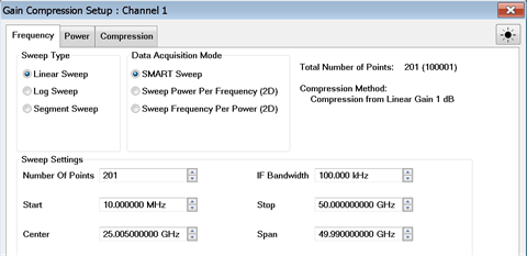
Configures the frequency settings over which Gain compression is to be measured, as well as the measurement method. Sweep TypeChoose a method in which to sweep frequency: Linear, Log, and Segment Sweeps. This setting applies to all data acquisition modes.
Data Acquisition ModeSpecifies HOW the gain compression data is collected. SMART Sweep
2D (two-dimensional) Sweeps
Sweep SettingsClick each to learn more about these settings.
Data Points LimitThe maximum number of measurement data points depends on Acquisition method and Compression method as follows:
Note: Although the dialog box will allow you to enter any number of frequency or power points, the values are checked when OK or Apply is pressed. If a limit is exceeded, the relevant data points are reduced to the maximum allowable number without warning. |
|
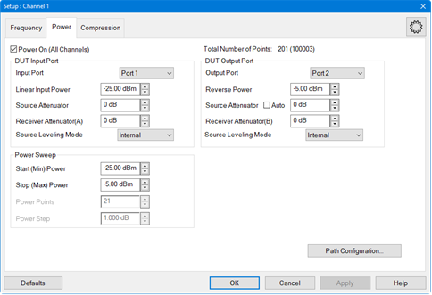
Configures RF power and Power Sweep settings for Gain Compression measurement. Power ON (All channels) Check to turn RF Power ON or clear to turn power OFF for all channels. Input PortSelect the VNA port that is connected to the DUT Input. Linear Power Level The input power that yields the linear gain of the DUT. The linear gain is used as the reference gain when calculating the Compression from Linear Gain. Input match is also measured at this power level. Receiver Attenuator Specifies the attenuator setting for the receiver associated with the output of the DUT. When the power into the receiver test port is around +10 dBm, the VNA receiver may be in compression. However, with receiver attenuation, lower input power levels may become too noisy to make accurate power measurements. In this case, lower IFBW to reduce noise. Learn more about Receiver Attenuation. (This only applicable for PNA and M9485A) Source Leveling Mode Specifies the leveling mode. Choose Internal or Receiver R1. Learn how to configure Receiver Leveling. Open Loop should only be used when doing Wideband Pulse measurements. Receiver Attenuator Specifies the attenuator setting for the receiver associated with the output of the DUT. When the power into the receiver test port is around +10 dBm, the VNA receiver may be in compression. However, with receiver attenuation, lower input power levels may become too noisy to make accurate power measurements. In this case, lower IFBW to reduce noise. Learn more about Receiver Attenuation. (This only applicable for PNA and M9485A) Source Leveling Mode Specifies the leveling mode. Choose Internal or Receiver R1. Learn how to configure Receiver Leveling. Open Loop should only be used when doing Wideband Pulse measurements. Output PortSelect the VNA port that is connected to the DUT Output. Reverse Output Power Sets power level into the output of the DUT for reverse sweeps. Port power is automatically uncoupled. Reverse power is applied to the DUT ONLY under the following conditions. Otherwise, this setting is ignored.
Receiver Attenuator Specifies the attenuator setting for the receiver associated with the DUT output port.(This only applicable for PNA and M9485A) Source Leveling Mode Specifies the leveling mode. Choose from: Internal (normal operation) or Open Loop (used only for Wideband Pulse measurements). Receiver Attenuator Specifies the attenuator setting for the receiver associated with the DUT output port.(This only applicable for PNA and M9485A) Source Leveling Mode Specifies the leveling mode. Choose from: Internal (normal operation) or Open Loop (used only for Wideband Pulse measurements). Power SweepPower Points Number of power points to measure for 2D acquisition modes. The Power Points may be limited due to the number of frequency data points. See Data Points Limit. This setting is NOT available in SMART Sweep, which uses only enough power points to find the specified compression level. Start and Stop Power
Power Step (Size) Calculated value from current Start, Stop, and Points settings. This setting can NOT be changed directly. |
|
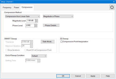
Compression MethodLearn ALL about these Compression Methods
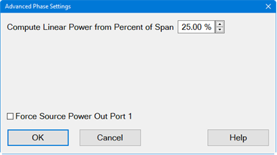
PhaseNote: Gain Compression Phase is a Licensed Feature. Learn more about Licensed Features. When Compression from Linear Gain is selected and the Data Acquisition Mode in the Frequency tab is set to Sweep Power Per Frequency (2D) or Sweep Frequency Per Power (2D), the following Phase functions are enabled. Magnitude Only Measures compression against magnitude. Phase Only Measures compression against phase. Magnitude or Phase Measures compression against magnitude or phase. Phase Level Specifies the phase to interpolate compression point. Phase Details... Accesses the Advanced Phase Settings dialog. Gain Compression Measurement Class Dialog
Gain Compression Converters Measurement Class Dialog
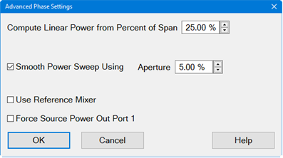
Compute Linear Power from Percent of Span Specifies the aperture as a percentage of span to compute linear input power. Smooth Power Sweep Using Enables the power sweep to be smoothed. Aperture Aperture used for smoothing the power sweep. Use Reference Mixer Enables a reference mixer. To improve the noise of the phase measurements in Gain Compression Converters (GCX), an optional user supplied external reference can be added to the R1 loop. The LO for the reference mixer should be common with the LO for the DUT mixer. After this hardware is added, and this function is enabled, the GCX application will use the reference mixer to improve the phase measurements. Force Source Power Out Port 1 This function is used when GCX channels with a reference mixer and one GCA channel without a reference mixer are set up simultaneously and you want to use the same path configuration for all channels. This remaps the source port to Port 1. SMART SweepTolerance Specifies an acceptable range for measuring the compression level. Reducing this value can significantly increase the number of iterations that are required to find the compression point. Maximum Iterations Specifies the maximum number of power search iterations SMART Sweep is allowed. Reducing this value can cause SMART sweep to terminate before all compression levels are found to within the specified tolerance. Show Iterations When checked, the compression parameter traces are updated at the completion of each power search iteration. When cleared, compression parameter traces are updated when SMART Sweep completes the power search iteration process. 2D Sweep - Compression Point InterpolationWhen a 2D Sweep is selected (on the Frequency tab), check this box to calculate and display interpolated compression traces. The Target gain is calculated using a complex linear ratio between the two closest measured values. All compression parameters are then interpolated using this same ratio. Clear the box to display compression parameters for the closest compression point, either high or low, to the level specified in the Compression Method setting. End of Sweep Condition Specifies the power level applied to the DUT at the completion of a GCA measurement. GCA performs numerous power and frequency sweeps on the DUT during the overall measurement process. This setting has no affect on these intermediate sweeps. This setting only applies at the end of the very last sweep in the GCA channel. In addition, this setting applies ONLY to the GCA channel. All other channels operate independently of this setting. Therefore, the power applied to the DUT after all channels have been measured may be different from this setting. Choose from:
Settling TimeUsed ONLY in SMART Sweep when Back Off or X/Y compression algorithms are selected. This setting allows additional dwell time when the input power changes from the back-off level to the compression level. Learn more.
|
|
For use with SMART Sweep ONLY. When enabled, Safe Sweep increases the input power to the DUT by the specified amounts, allowing the compression point to be achieved gradually. While this will increase the number of iterations required to achieve compression, it also minimizes the possibility of driving the DUT too far into compression. Note: Safe Sweep does NOT minimize the dramatic change in input power with Backoff and XY method. However, Safe Sweep with Backoff and XY methods DOES prevent the DUT from being exposed to too much input power. Learn more. Safe Mode (Enable) Check to enable Safe Sweep. Coarse Increment Sets the maximum change in input power, up or down, which will be applied to the DUT from one iteration to the next. Default = 3.0 dB. Without Safe Sweep, the maximum change in input power can be the entire Backoff or X value when using these compression methods. Fine Increment Once the Fine Threshold has been achieved, this becomes the maximum change in input power, up or down, which will be applied to the DUT. Default = 1.00 dB Fine Threshold Specifies the compression level in which Safe Sweep changes from the COARSE to the FINE increment. Default = 0.5 dB. This means that, by default, the VNA uses the Fine Increment adjustment when compression reaches 0.5 dB. Max Output Power To protect the VNA from damage, when the VNA port that is connected to the DUT Output measures the specified value, the input power to the DUT is no longer incremented at that frequency. In these cases, the compression point would probably not be achieved. DC Parameters Select a DC device from the pulldown list. (Modification Distortion Only) Note: When a DC meter is added, it will be displayed in the New Trace dialog and SMART Sweep Safe Mode dialog (in DC Parameters pull down menu). Max DC Power Enter the limit value of the DC device. When the Max DC Power is above the limit value, the power sweep is clipped and returns to the previous safe value. The units are changed automatically per the Type setting in the DC meter dialog. (Modification Distortion Only)
|
Compression Analysis changes the current trace into a power sweep trace at a specified CW frequency . The current parameter and acquisition method is unchanged. For example, with a CompGain21 trace displayed and SMART Sweep selected, enable Compression Analysis. The trace becomes a power sweep trace at the specified CW frequency. The Y-axis displays S21 Gain at each X-axis power point.
When Smart sweep is used, a complete power sweep is not performed, but only the data points that are required to find the compression point. To see a traditional power IN vs power OUT compression sweep, use one of the 2-D acquisition methods.
You can create PNOP or PSAT markers on a CompOut trace with Compression Analysis mode ON. Learn more.
How to perform Compression AnalysisWith any compression parameter (such as CompGainS21) displayed: |
|
|
Using Hardkey/SoftTab/Softkey |
Using a mouse |
|
|
|
Compression Analysis dialog box help |
|
Notes: When an S21 or S11 trace is active, any compression parameter (such as CompGainS21) must also be displayed. Compression Analysis is NOT allowed for S12 or S22 traces. Scroll up to learn more about Compression Analysis. Analysis Frequency: CW Enter a frequency to use for the compression analysis trace. Compression Analysis Check to perform compression analysis. A compression trace is displayed at the Analysis (CW) Frequency. Use Discrete Frequencies Check to allow Analysis Frequencies at only the discrete points where data is measured. Clear to allow Analysis CW Frequencies that are interpolated from the data points. Then select ANY CW frequency between the start and stop frequencies of the GCA channel. X-Axis
|
Beginning with VNA release A.08.20, GCA data can be saved to a *.csv file in both 2D and SMART Sweep modes (previously only 2D modes). Also, a Delta Gain, AI1, and AI2 columns have been added to the data. Learn about ADC parameters.
How to save GCA dataWith a GCA Compression trace active: |
|
|
Using Hardkey/SoftTab/Softkey |
Using a mouse |
|
|
Notes
This data type can be read by spreadsheet programs, such as Microsoft Excel.
Data from the last complete sweep is saved to the specified *.csv file.
If calibration is turned ON when the file is saved, then all data is calibrated. Otherwise, raw data is saved.
All *.csv data saves include a reference power level sweep at the beginning of each frequency data.
GCA Sweep Data (*.csv) includes sweep data.
SMART Sweep data with 5 iterations and 3 frequency points. The yellow highlight is added here for readability.
When Linear Input Power EQUALS Start Power, then the number of data points (rows)/ freq = num power points.
When Linear Input Power does NOT EQUAL Start Power, the number of data points (rows)/ freq = num power points + 1.
Make these selections on the GCA/GCX Power tab dialog.
There are many settings in the Gain Compression Application. Here are a few tips when using GCA to learn as much as possible about the compression characteristics of your DUT in the most efficient manner.
Although GCA provides excellent results with a wide variety of amplifiers, it works best with amplifiers which have a monotonic compression curve. In some cases where the compression curve is not monotonic, for example if the amplifier gain expands before it compresses, the correct compression level may not be found.
To help a SMART sweep find the correct compression point, limit the Start and Stop power levels around the anticipated compression point. Learn more.
The following two power-sweep traces are examples of non-monotonic gain:
A DeltaGain trace is the best way to see how closely GCA is actually measuring to the desired compression level. In addition, you can view the phase of DeltaGain to see the phase deviation between the compressed gain and the reference gain. DeltaGain is calculated as:
DeltaGain = Measured Gain (watts) / Ref Gain (watts)
In LogMag format: DeltaGain = (Measured Gain) - (Ref Gain)
With SMART Sweep, DeltaGain (in LogMag format) shows how soon certain frequencies achieve the specified tolerance. Learn more.
Some other settings which may be helpful:
Trigger source: Manual allows you to analyze data and make adjustments while allowing the device to cool.
Construct Limit Lines around the compression point at the tolerance level.
The following image shows a DeltaGain21 trace using SMART Sweep. The Limit Lines were added manually.
In the above image:
|
Relevant Settings |
Method = Compression From Linear Gain Compression level = 1 Iteration Tolerance = 0.05 dB. Maximum Iterations = 10 |
|
Displayed Results |
A data point on -1.00 indicates that, at that frequency, the exact compression level (1 dB) was measured. Several frequencies did not achieve the specified tolerance (0.05 dB) before the Max Iterations (10) was reached.
|
Compression from Linear Gain is the easiest compression method to understand and control in SMART Sweep. Learn more.
If SMART Sweep requires more than twenty iterations, this is an indication that something is wrong. Try changing the Tolerance setting, Frequency Range, Start / Stop power range, IF bandwidth, or Dwell Time.
If the number of iterations required to achieve the desired compression level changes significantly from one set of measurements to the next, this could be due to other effects, such as heating. Try increasing the dwell time or using a wideband pulse measurement configuration.
If the DUT should not be significantly overdriven into compression, or the changes in the input power should be limited, use Safe Sweep mode with Deviation from Linear Gain compression method.
The macros perform a single power sweep on the DUT using a standard channel with corresponding stimulus settings. The macro can show measurement differences from the compression analysis traces due to bias/thermal/settling effects of the DUT. So, the macro can help confirm a DUT is exhibiting some type of settling behavior which will need to be handled in some way.
Also, the macro is a great GCA programming example.
With a 2D sweep (NOT SMART Sweep) a script that is stored on the VNA hard drive automatically creates a traditional power sweep measurement in a standard channel using the same stimulus setting as the GCA channel. Use a marker in the GCA channel to specify the frequency for the measurement.
The script has two modes of operation:
View Mode displays all of the previous 2D sweep data at that frequency.
Measure Mode performs a new measurement at that frequency.
Both modes create a new S-Parameter channel using the same stimulus settings as the GCA channel, including port power, attenuator, IF Bandwidth, and dwell settings. The new channel does not support calibration or pulse characteristics.
To see noise on a measurement, use the Measure macro in continuous sweep. Adjust the IFBW and averaging until the noise versus sweep speed meets your needs.
To see other effects of your DUT at a specific frequency, use the View macro and the Measure macro with 2D sweep mode. Both macros present data using a standard channel. The View macro shows 2D data at a specific frequency, while the Measure macro shows freshly-measured data at the same frequency. Ideally, the data from these two would be identical. However, changes in your DUT behavior due to heating or other effects can cause these to be different. If significant differences exist, try:
Using the 2D Frequency per Power setting rather than Power per Frequency
Adjusting the dwell time
Adjusting IFBW
Each macro must be setup separately.
Press Macro > Key Setup > Macro Setup....
Select a blank line, then click Edit.
In Macro Title, type a short description such as Meas GCA or View GCA.
Click Browse, then navigate to C:\Program Files(x86)\Keysight\Network Analyzer\Applications\GCA\GCA.vbs
In Macro run string parameters:
Type M for the Measure macro or V for View macro.
Optional: Supply the following additional parameters in any order:
To run the program from a remote computer, specify the full computer name of the VNA .
Channel in which to create the measurement. If not specified, Measure is created in Ch30 and View is created in Ch31.
Example: Run string parameters for the Measure macro run from a remote computer in Channel 5.---- M MyVNA 5.
Click OK.
On a GCA channel:
Create a 2D sweep. Either Power per Freq or Freq per Power. Both macros always create a power sweep at the frequency of interest.
Create a CompIn trace.
On the CompIn trace, right-click and select Add Marker. Drag the marker to the frequency of interest.
Press Macro, then select either by the short description your provided in Step 3.
This feature is available when VNA has Option 086 with support date 2024.0101.
This feature enables the multiple GCA channels to be swept in parallel when more than one GCA channels are created. The parallel can only be turn ON/OFF by sending SCPI commands.
To enable the parallel measurement, these conditions should be met:
Only support PXI-VNA platform.
GCA Channel Setup
Data acquisition mode "SMART Sweep" is not allowed.
Receiver Leveling is not allowed.
Secondary channels' setup must be same as the primary channel, except:
DUT input ports can be set to different (or same) VNA ports.
DUT output ports must be set to different VNA ports.
For multiple input and multiple output DUT, recommend setup channels using test port 1 and test port 2 for channel 1, test port 3 and test port 4 for channel2, etc.
Port 1 and port 2 on same module cannot be DUT input ports at same time;
For 4/6-port modules, port 3 and port 4, or port 5 and port 6 on same module cannot be
Correction Method
If DUT input ports are set to different VNA ports, both Enh Resp cal and 2P cal are allowed;
If DUT input ports are set to same VNA port, 2P cal is not allowed.
Meas Parameters
If DUT input ports are set to different VNA ports, all parameters are allowed;
If DUT input ports are set to same VNA port, linear reverse isolation trace is not allowed.
PMAR trace is not allowed.