System Receiver Cal is a SERVICE Routine for performing the enhanced mixer calibration for the VNA. This calibration should be performed when Option 009 is installed for performing SMC measurements.
NOTE: The is available for M937xA and P937xA only.
Note: The power sensor depends on the VNA frequency range. Depending on the VNA model, two power sensors may be required to test the full frequency range. The VNA front panel connector type will determine the cable used and if an adapter is required with the power sensor(s).
External Source
See list of supported power meters and sensors.
Note: Throughout this procedure, an M937xA is shown.
Connect the controller to the power meter/power sensor and also to your external source using GPIB or USB.
Launch the soft front panel of the VNA.
Click Utility, then System, then Service, then Adjustment Routines.
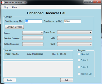
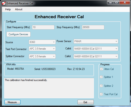
At the Adjustments selection, click System Receiver Cal. The Enhanced Receiver Cal dialog is displayed as shown below.
Click the Configure Devices button to configure an external source and PMAR (Power Meter as a Receiver).
In the Enhanced Receiver Cal dialog, set up the following:
Enter the Start Frequency and Stop Frequency.
Select your external source from the Source drop-down menu.
Select your power sensor from the Power Sensor drop-down menu.
Select the test port connector type of the VNA and corresponding calkit from the Test Port Connector and Calkit drop-down menus.
Select the splitter connector type and corresponding calkit from the Splitter Connector and Calkit drop-down menus.
Click the Begin button to start the calibration process.
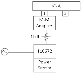
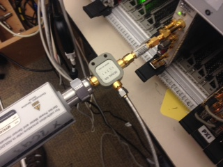
On port 1 of the VNA, connect a male-to-male adapter and then a 10 dB attenuator as shown below.
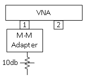
In the Enhanced Receiver Cal dialog click the Measure button to perform a 1-port S-parameter calibration at the end of the attenuator.
When prompted, connect an ECal module to the end of the 10 dB attenuator on port 1 then click OK.
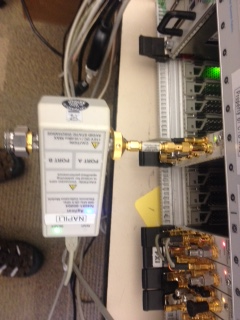
When prompted, connect a splitter as follows.
Connect the external source to the input of the splitter.
Connect one splitter output to the end of the 10 dB attenuator on port 1.
Connect the power sensor to the other splitter output.
Connect the 10 MHz reference OUT from the VNA to the 10 MHz reference IN of the external source.
Click the Measure button (this measurement may take up to 2 minutes to complete).
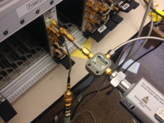
When prompted, disconnect the splitter and flip the connections as follows.
Connect the 10 dB attenuator on port 1 to the opposite output of the splitter.
Connect the power sensor to the opposite output of the splitter.
Reconnect the external source to the input of the splitter.
Click the Measure button (this measurement may take up to 2 minutes to complete).
When prompted, disconnect all cables and adapters from port 1 and port 2.
Click the Measure button to perform a 2-port S-parameter calibration at the test ports.
When prompted, connect the ECal module to port 1 then click OK.
Note: If you have an insertable ECal module, then you can connect it directly to the ports. If the ECal module has female connectors, then an adapter will be needed.
When prompted, connect the ECal module to port 2 then click OK.
When prompted, remove the ECal module and connect a cable from port 1 to port 2 then click OK. Ensure that the cable has a frequency range that spans the frequency range of the VNA.
When finished, a message indicating that calibration was successful is displayed.
The correction data is stored in the flash memory.