When a power meter is configured as a VNA receiver (in standard measurement channels ONLY), you can...
Extend the number of measurement receivers.
Use the power meter as a scalar detector.
Monitor the power at any point in a measurement system.
Use multiple power meters in a Guided Power Cal to cover a wide frequency range.
Note: Multiple configurations for the same physical device can be Active. However, only one configuration for the same external source can have the I/O Enabled
Use the power meter to level the stimulus power at any point in a measurement system.
Use the power sensor as a PMAR device to confirm the accuracy of a Source Power Cal. Learn how.
Note: PMAR is not compatible with Point Sweep mode.
Once configured, a power meter can be used like any other VNA receiver in the following dialogs:
New Trace / Meas dialog - used in Ratioed and Unratioed measurements.
Frequency Offset Mode - Extend frequencies beyond VNA
Important first-time USB connection note.
How to Create and Configure a PMAR Device
VNA Applications have additional methods of launching this dialog. |
|
|
Using Hardkey/SoftTab/Softkey |
Using a mouse |
|
|
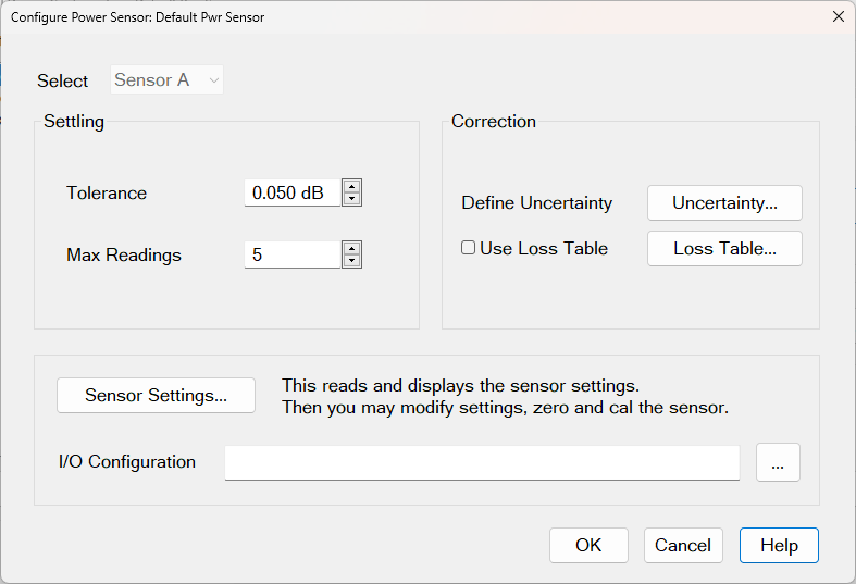
Screen 1. Click Sensor Settings to access additional parameters (see Screen 2a and Screen 2b)
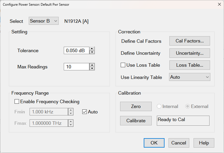
Screen 2a. Sensor Settings with no internal cal factors
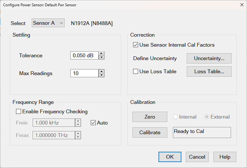
Screen 2b. Sensor Settings with internal cal factors
Parameter DescriptionsSelect From this drop-down menu, select one of up to four power sensors. If a sensor was not previously configured, "Sensor A" is displayed and remains grayed out (inactive) until you enter a valid I/O Configuration address and click Sensor Settings. Then you can select a sensor from the menu. The power meter model appears in brackets to the right of the selected sensor model. Note: When configuring the "Default Pwr Sensor," if you change the enabled sensor from Sensor A to Sensor B, then the settings for Sensor A will be saved and are not affected by new Sensor B settings. This supports legacy Default Sensor Auto-Switching, where the VNA automatically switches between default sensors if the selected sensor cannot cover the desired frequency range. Sensor Settings This button appears when the dialog is first opened. Clicking this button reads the sensor and updates the information on this dialog. I/O Configuration This field operates the same as "I/O Configuration" in the "External Devices" dialog. This is provided for your convenience. If you try to read sensor settings without a valid I/O name, you can enter a valid I/O here and try again. SettlingTolerance This value used for sensor settling. When two successive measurements differ by less than the tolerance value, then the sensor is considered to be settled, and the last measurement is used. Tolerance has a special case where a tolerance of 0 will always just return an averaged reading that is simply the mean of Max Readings.
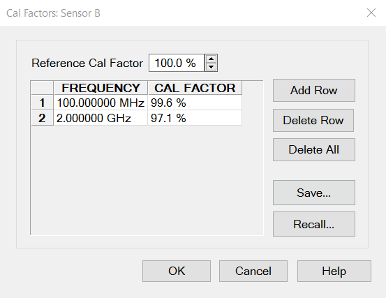
Max Readings Maximum number of readings allowed for sensor settling. Default is 10. CorrectionDefine Cal Factors The label (and button) are not displayed until you click the Sensor Settings button. If the sensor's EEPROM contains cal factors, then the Use Sensor Internal Cal Factors checkbox is displayed and is selected by default. If you deselect it, no cal factors are used. If the sensor's EEPROM does not contain cal factors, then Define Cal Factors and the Cal Factors... button appears. Click the button to open the "Cal Factors" dialog (shown below) to define the cal factor table.
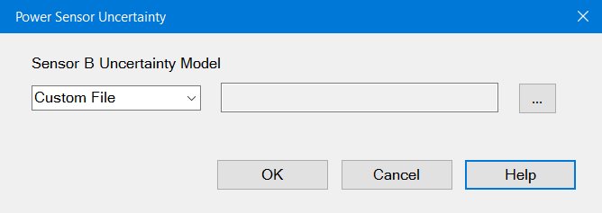
Uncertainty... This button opens the "Power Sensor Uncertainty" dialog (shown below) to either select a specific power meter from a list or load a custom file of power meter uncertainties. This sets up power-meter uncertainties for power-uncertainty calibrations. Then, when the Calibrate Uncertainty checkbox is selected during a guided calibration, uncertainty power values will include the uncertainty of the power meter.
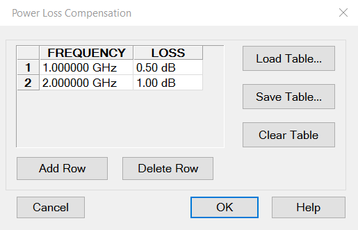
Use Loss Table When enabled, offsets the sensor readings by the loss table. This checkbox is disabled by default. Clicking the Loss Table... button opens the Power Loss Compensation dialog, where you can view or edit the loss table.There is a different loss table for each sensor. Use Linearity Table The checkbox (and button) are not displayed until you click the Sensor Settings button. Select from either Auto (default) or D-Type. Auto (default) The power meter queries the sensor and automatically selects between A-Type and D-Type linearity tables. D-Type The power meter is forced to use the D-Type linearity table. Note: The checkbox (and button) are not displayed if the power meter is not one of these models: E4416A, E4417A, N1913A, and N1914A. This is verified by sending the SCPI query "SENS:V2P?" and checking to see if this error occurs: -113,"Undefined header;sens:v2p?" This indicates that the meter doesn't support the V2P command. Note: The checkbox (and button) are not displayed if the power sensor is not one of these models: W8486A, E8486A, V8486A, N8486DG-100. This is verified by sending the SCPI query "SERV:SENS:TYPE?" and verifying that it returns a single letter (A, B, D, H) rather than a model number. This occurs because the sensor has no EEPROM for the model number. Note that this results in a false positive if the 8482A is connected, because even though it should use the A-Type table, the firmware allows you to switch it to Type-D. Frequency RangeEnable Frequency Checking This checkbox is disabled by default. This checkbox is set independently for each selected sensor. When enabled, the VNA ensures that the sensor is only used over its defined frequency range during calibrations and normal measurements. Auto Switching: For all sensors (both default and others), if "Enable Frequency Checking" is enabled for a selected sensor, then "Source Power Cal" and "SMC Smart Cal" automatically switches between the A, B, C, and D sensor channels if one sensor channel cannot cover the full frequency range of the calibration. In the legacy VNA firmware, this feature was only available for the Default Power Sensor and not other sensors. Fmin, Fmax These frequencies are used by the VNA to perform Frequency Checking. You can modify the frequencies even if "Enable Frequency Checking" is disabled. Auto When enabled, this checkbox automatically loads Fmin and Fmax from the sensor and grays out the Fmin/Fmax entries. If Auto is disabled, you can enter Fmin and Fmax values manually. This is enabled by default if the sensor includes Fmin and Fmax values. If the sensor cannot provide Fmin and Fmax values, then the Auto checkbox will be unchecked and grayed-out so it cannot be selected. Fmin defaulta to 0 Hz and Fmax defaults to 1 THz. CalibrationFor highest accuracy, Zero and Calibrate the power sensor before measuring data. Follow any prompts that may appear. Zero If the following settings are 'grayed', Internal or External zeroing is selected automatically based on the power meter/sensor model. Otherwise, select the appropriate type oFroing to perform, then press Zero. Internal (zero) A switch inside the power sensor removes the sensor from the incident power. External (zero) Requires that you physically remove the sensor from incident power. Calibrate Available when the selected sensor has calibration capability. Calibration involves measuring an internal 1 mW source. Follow any prompts that may appear.
Calibration Status This field, to the right of the Calibrate button, displays seven possible messages:
|
|
To Add a Row to the table, click on a row in the table and press the down arrow on either the VNA front panel or keyboard. To Edit a value, double-click in the cell to be edited. Compensates for losses that occur when using an adapter or coupler to connect the power sensor to the measurement port. These components will be removed when the calibration is complete. To account for components that will remain during the measurement, use the Power Offset setting. The Frequency / Loss pairs define the amount of loss for the entire frequency range. For example, using the entries in the above dialog image:
Frequency Enter a frequency in Hz. Loss Enter a loss as a POSITIVE value in dB. To compensate for gain, use NEGATIVE values. Load Table Load Table Import power loss values directly from a CSV file. The CSV file must contain one <frequency (Hz), loss(dB)> pair per line separated by a comma. This method is ideal for users working with hundreds or thousands of frequency-loss pairs. Example: 1e+09,0.5 2e+09,1 Save Table Saves the table to a CSV file. Delete Row Deletes the row currently highlighted. Clear Table Deletes all data in the table. The Power Loss Compensation table survives VNA Preset and Power OFF. To not use loss compensation, clear the Use Loss Table checkbox on the Configure Power Sensor dialog. |
Learn how to create and configure PMAR device.
After a Source Power Cal has been performed, use the same sensor as a configured PMAR to analyze the accuracy of the Calibration.
Create a PMAR device with the power sensor that will be used for the Source Power Cal.
Perform a Source Power Cal. Learn how.
Create an unratioed measurement with the PMAR device. Learn how.
With the power sensor still connected to the test port, monitor the corrected source power using Min and Max markers or the Trace Statistics peak-to-peak feature.