The following information is unique to SMC:
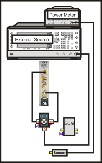
SMC requires a power meter/sensor, two sources, and a Cal Kit or ECal module
Your DUT can be connected to any VNA ports. Learn more.
Connect External Source to the VNA GPIB Controller port. Learn how to Configure an External Source.
Connect the 10 MHz reference signal of an external source to the VNA.
Use either a GPIB power meter or USB power sensor.
Press Setup > Main > Meas Class....
Select SMC, then either:
OK delete the existing measurement, or
New Channel to create the measurement in a new channel.
An SC21 measurement is displayed.
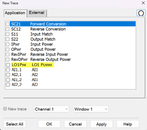
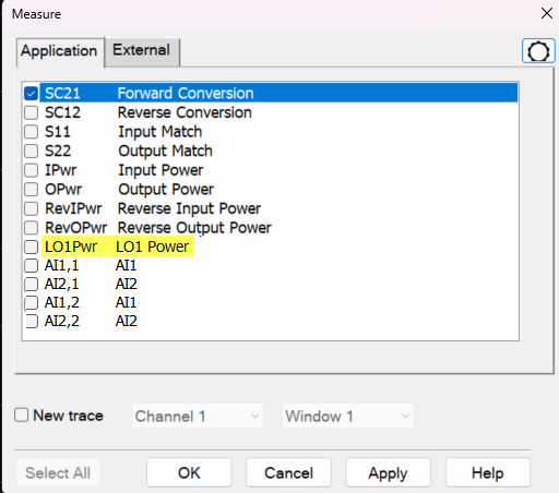
To display additional parameters, press the Trace hardkey then right-click the graticule and select New Trace... (or select the New Traces... softkey). The New Trace dialog appears. Select a parameter from the list (shown below). You can also access the Measure dialog (shown below) by pressing the Meas hardkey and then selecting the Other... softkey.
See also, Measurement Parameters.
Note: The LO power parameters (LO1Pwr and LO2Pwr) appear only when you configure an internal LO source. LO2Pwr appears only when you have configured a 2-stage mixer and the 2nd LO is an internal port. Learn more.
External Select external receiver traces (e.g. Power Meters. DC Meters, SMUs)
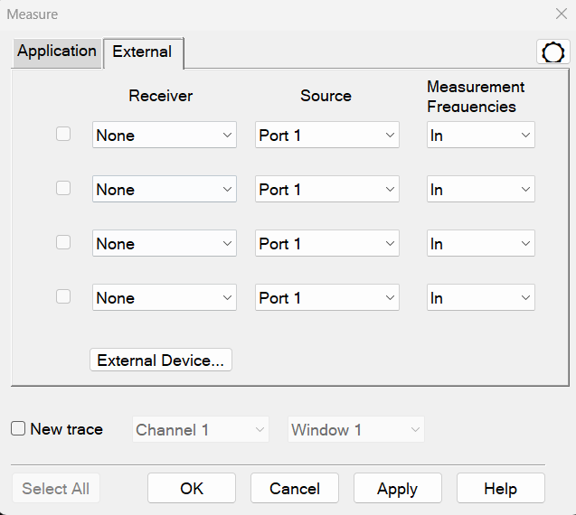
Receiver Allows users to select the external receiver. Will show all external receivers (Power Meter, DC Meter and SMU) defined in the External Device Configuration dialog which have "Active - Show in UI" enabled.
Source User may select between both input and output DUT/ Mixer port as source.
Measurement Frequencies The measurement frequency range of the receiver is identified by selecting a DUT port in this column. For mixers, the receivers may measure four frequency ranges: In, LO1, LO2, Out.
Parameter Naming:
The active source will be appended to the receiver's name following a comma (,). Example: MyPMAR,1
The frequency range will be appended to the name of the sensor following an underbar character (_). Example: MyPMAR_Out,1
The frequency range is only available for PMAR external receivers.
External Device... Click on this button will open the External Device Configuration dialog.
New trace Click to allow multiple external receiver traces to be selected. If "New Trace" is enabled, then multiple check-boxes maybe selected.
|
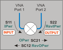
Important Note: Connecting your DUT to the VNA: RF and IF terminology is NOT used in FCA because the VNA does not know how the DUT is labeled or how it will be used. Instead, the general terms INPUT and OUTPUT are used.
INPUT and OUTPUT Frequencies are specified using the Mixer Setup dialog box. |
|
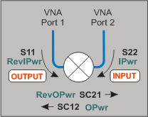
The DUT input and output can be connected to any VNA ports. Note: Although there are MANY configuration possibilities, the following images and descriptions show ONLY a DUT connected to VNA ports 1 and 2. Legend: Black are ratioed measurements (test port/reference receiver). Green are unratioed measurements (either a test port OR reference receiver). |
|
DUT Input to VNA port 1 DUT Output to VNA port 2 |
DUT Input to VNA port 2 DUT Output to VNA port 1 |
|
|
|
|
Ratioed
|
Ratioed
|
|
Unratioed Absolute test port receiver measurements. The receiver is automatically selected depending on the DUT configuration.
|
|
The following SMC Mixer Setup dialog tabs are presented:
Sweep Tab (shared with VMC)
Power Tab (shared with VMC)
Mixer Freq Tab (shared with all converter apps)
Mixer Power Tab (shared with all converter apps)
Mixer Setup Tab (shared with all converter apps)
Using default SMC settings, any calibrated SMC measurement requires four sweeps. However, you can reduce the number of sweeps required by selecting one or more of the following settings.
To speed up a Swept LO measurement when using an external source for the LO, use Hardware List (BNC) Trigger setting . Learn more.
Click Response, Cal, Correction Methods..., and then Use Nominal Incident Power checkbox.
Each data sweep of a fully corrected SMC transmission measurement actually requires FOUR data sweeps. When you clear Use Nominal Incident Power, the reference receiver (R1 or R2) does NOT measure incident power. Instead, the incident power is assumed to be at the level that was set with the Source Power Calibration that is done as part of every SMC measurement. The degradation in accuracy is very negligible if the input or output of your DUT is well-matched.
This selection eliminates sweeps ONLY when both Include Input Match AND Include Output Match is cleared on the Cal Type dialog. Learn more.
You can create an FCA measurement and apply an existing Cal Set as you can with any VNA measurement. Learn about Cal Sets. In addition, from a Cal Set, you can apply a specific SMC Cal Type to an existing SMC measurement.
How to apply an SMC Cal Type
|
Using Hardkey/SoftTab/Softkey |
|
|
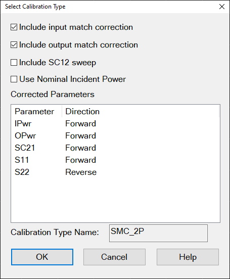
By default, each SMC calibration requires FOUR sweeps. Clearing boxes will eliminate sweeps and speed up your SMC measurements. The difference in speed is most noticeable when making fixed input or fixed output measurements with an external LO source. Include input match correction Check to perform a sweep to measure and correct for INPUT match. Clear this box if the input of your mixer is well-matched to the VNA, or if your setup does not permit a valid S11 measurement. Include output match correction Check to perform a sweep to measure and correct for OUTPUT match. Clear this box if the output of your mixer is well-matched to the VNA, or if your setup does not permit a valid S22 measurement. Include SC12 Sweep Check to perform a reverse sweep to measure SC12.
Corrected Parameters Lists the parameters that can be corrected given the boxes that are currently checked. These parameters may not be currently measured. Calibration Type Shows the type of SMC Cal that will be applied given the boxes that are currently checked. Learn about Use Nominal Incident Power How many sweeps can be eliminated?
*S11 shares a sweep with IPwr and S22 shares a sweep with RevIPwr. Therefore, when Include Input Match or Include Output Match is checked, then checking Nominal incident power does nothing. VMC measurement sweeps can NOT be eliminated. |
Note: [M937xA/P937xA] Before SMC Calibration, perform the System Receiver Cal. The Cal All Wizard guides you through the calibration process.
The SMC Calibration Wizard guides you through this process.
When applying a Phase Reference cal set, step 1 (power cal) is NOT performed.
Connect a power meter / sensor to VNA Port 1. At each step of the input and output frequency, the VNA measures:
input match of the power sensor
source power of the VNA
Perform two Full 2-port calibrations: one over the INPUT frequencies and one over the OUTPUT frequencies of the DUT. (If your DUT is a linear device, the calibration uses only the INPUT frequency range.) Use either a mechanical calibration kit or an ECal module.
The Unknown Thru method is NOT valid when there is over 40 dB of combined loss in the Unknown Thru and calibration path. In this case, the following calibration and correction method is recommended.
On the Cal Wizard Modify Frequency page, select Defined Thru or Flush Thru as the Thru method. When using an ECal module, also on the Modify Frequency page, disable (clear) Do Orientation due to very low power.
After calibration, on the Correction Method dialog, CLEAR the Include output match correction and Include SC12 Sweep check boxes. Check ONLY Include input match correction.
To learn more about High-power measurements, see our App Notes.
NOTE: The Smart Cal wizard is not available for the M937xA/P937xA
The following dialog boxes are presented during an SMC Calibration.
Indented steps are optional.
How to Perform a SMC Calibration
|
|
Using Hardkey/SoftTab/Softkey |
Using a mouse |
|
|
|
Allows you to review and change the settings for your SMC calibration. Note: With release A.09.90 and before, checking both 'Independent power cals' AND 'Use Phase Reference Calset' would generate an error after performing the calibration. With releases AFTER A.09.90, the two settings are compatible. Waveguide/In-fixture/On-Wafer Setup Click Next to launch the following Setup dialog box. Independent power cals for input and output ports (no thru) Check if a Thru standard is NOT available. During the power cal, you will be prompted to connect the power sensor to the Input, then the Output port. Additional Power Cal StepsEnable LO1 / LO2 Power Cal Check when LO1 / LO2 is controlled (on the Mixer Setup tab) to perform a Power Cal on the LO source(s). Phase CorrectionEnable Phase Correction Check to enable Phase measurements. Choose one of the following methods to specify the delay through the characterized mixer. With the first two methods, the phase delay through a Calibration Mixer is measured and compared to the known delay, either entered, or stored in an *.S2PX file.
|
|
This dialog box appears ONLY if you checked the Waveguide/In-fixture/On-Wafer Setup box in the previous Cal Setup dialog. Allows you to embed or de-embed circuit networks on the input and output of your mixer under test. For Network1 (Input) and Network2 (Output) select Embed, De-embed, or None. Browse Click to navigate to the .S2P file that models the network to embed or de-embed. Reverse port positions for input/output Check to cause the Fixture/Adapter to be configured with Port 2 connected to the VNA and Port 1 to be connected to the DUT. The image in the dialog is updated to reflect that change. Enable Extrapolation Check (default setting) to apply a simple extrapolation when the S2P file has a narrower frequency range than the channel. The values for the first and last data points are extended in either direction to cover the frequency range of the measurement. A warning message is also displayed when extrapolation is necessary. To Embed or De-embed
|
|
Allows you to specify the connector type and Cal Kit for each DUT port. Port n For each listed VNA port, specify the DUT connector type and gender, and the Cal Kit to use. Note: If your DUT connectors are:
Modify Cal Check, then click Next, to start the Modify Frequency Cal dialog. Source Cal Settings Click to start the Source Cal Settings dialog. |
|
This dialog appears only when Modify Cal is checked on the previous dialog. The following selections are available ONLY if using an ECal module. Do orientation When this box is checked (default) the VNA senses the ECal model and direction in which the ECal module port is connected to the VNA ports. If power to the ECal module is too low, it will appear as if there is no ECal module connected. If you use low power and are having this problem, clear this check box to provide the orientation manually. Orientation occurs first at the middle of the frequency range that you are calibrating. If a signal is not detected, it tries again at the lowest frequency in the range. |
|
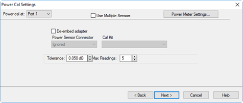
Power Cal at: Select the source port for which a Power Calibration will be performed. The source and receiver correction will be transferred to all other sources and receivers involved in the S-parameter measurements. Cal using From this drop-down menu, select from the following:
Note: Multiple Sensors is a licensed feature called "Multiple-sensor Power Calibration for SMC/GCX." Learn more about Licensed Features. Note: A Use Power Table drop-down menu (not shown) is available when any source port is using a table, such as a hybrid source or mmWave configuration. Learn more. Additionally, SMC requires that if one source port is using Multiple Sensor, PMax Table, or Import Power Cal, then the other source port must also use one of those methods and cannot use single sensor mode. Sensor Settings Opens the Configure Power Sensor dialog. This button appears when One Power Sensor or Multiple Sensors is selected. Sensor Name Select or add a power sensor. All power sensors are displayed in the list even if "Active - Show in UI" has been disabled in the External Device Configuration dialog. "Add Sensor..." opens the External Device Configuration dialog to the power meters page where you can configure more sensors. This drop-down menu appears when One Power Sensor or Multiple Sensors is selected. Note: Default Sensor Auto-Switching. This feature is only available for Source Power Cal and SMC Smart Cal (GUI or SCPI) when the "Enable Frequency Checking" checkbox is selected. It automatically switches the sensor channel (A - B - C - D) when the calibration frequency is out of range for the current sensor channel's specified frequency range. See also, Enable Frequency Checking. De-embed (power sensor) adapter When the power sensor connector is NOT the same type and gender as the DUT connector for the specified port, then for optimum accuracy, extra cal steps are required to measure and correct for the adapter that is used to connect the power sensor to the reference plane. Clear this box to NOT compensate for the added adapter. Check this box to perform extra calibration steps to measure and correct for the adapter. Then select the Power Sensor Connector type and gender of the power sensor. "Ignored" does NOT compensate for the added adapter, just as if the checkbox were cleared. When this connector matches the DUT connector for the same port, then the VNA assumes that there is no adapter. Extra cal steps are NOT required and the Cal Kit selection is not available. Otherwise, select the Cal Kit to be used to calibrate at the adapter.
Tolerance This value used for sensor settling. When two successive measurements differ by less than the tolerance value, then the sensor is considered to be settled, and the last measurement is used. Tolerance has a special case where a tolerance of 0 will always just return an averaged reading that is simply the mean of Max Readings.
Max Readings Maximum number of readings allowed for sensor settling. Default is 10. See Accuracy Settings below. |
|
This dialog box appears when the Do orientation checkbox in the previous Modify Frequency dialog box is cleared. Click the ECal Port that is connected to each VNA port. |
|
Power Level at which to perform the Power Cal. It is usually best to set power level to 0 dBm at the power sensor because the power sensor is calibrated at that level. Lower power levels will yield a slower and noisier calibration. If an external component is used between the PNA-X test port and the calibration reference plane, then adjust the power level so that the power at the sensor is about 0 dBm if possible. The current source attenuation value is shown on the dialog. LO Power Cal (Optional) When enabled, perform a Source Power Cal at the DUT LO connector. An LO must already be selected. Learn how. The power level of the LO source calibration is set on the (LO) Power Tab. |
|
Finish Save to the channel's calibration register. Save As User Cal Set Starts the Save as User Cal Set dialog box AND save to the channel's calibration register. Cancel Calibration is NOT applied or saved. Learn about Calibration Registers. Learn about User Cal Sets |
|
This dialog appears ONLY when Adapter Removal or Unknown Thru calibrations are performed. The following values were estimated from the measurement. Most of the time, they are adequate. However, for CW sweep or frequency sweep with large step sizes, the accuracy of the values may be improved. Adapter delay To improve this value, measure and record the delay of the adapter with a dense step size. Enter that value here. The required precision value is the accuracy that is required to characterize the delay value. Nominal phase offset (Waveguide ONLY). To improve this value, measure and record the phase offset of the Waveguide adapter with dense step size. Enter that value here. When one connector is coax and the other connector is waveguide, the phase offset has an ambiguity of 180 degrees. For consistency, the estimate provided here is always between 0 and 180 degrees. You can change this estimate to any value between -180 degrees and +180 degrees. For SMC calibrations, this dialog box appears twice: once for the input frequencies and once for the output frequencies. The values can be slightly different. |