Power Calibration
Note: It is recommended that SmartCal be used instead of the following Power Calibration procedures. The procedures in this topic are for those who cannot change their existing test program/procedure with their installed-base PNAs.
Note: Source and Receiver Power Calibrations are NOT available in M937xA/P937xA PXI.
Source and Receiver Power Calibrations work together to provide very accurate power levels from the source, and very accurate power measurements from the VNA receivers.
Other Source Power Cal choices
See other Calibration Topics
Source Power Calibration Overview
Note: Source and Receiver Power Calibrations are NOT available in M937xA PXI.
Perform Source Power Calibration when you need accurate power levels at some point in the measurement path between the VNA test ports. For example, you need to characterize the gain of an amplifier across a frequency range at a specified input power. You would perform a source power cal at the input of the amplifier to ensure the exact power level into the amplifier across the frequency range.
Using a Source Power Cal, you can expect the power at the point of calibration to be within the range of the uncertainty of the power meter and sensor that is used.
Source Power Calibration...
-
Is independent of measurement type. It corrects the VNA source regardless of which receivers are being used in a measurement. Therefore, it can be used with both ratio or non-ratio measurements.
-
Applies ONLY to those measurements on the selected channel that use the test port that was specified as the Source for the calibration. For example, if you specify Channel 1 and Port 1 as the source to be calibrated, only those measurements on channel 1 that use port 1 as the source will be corrected.
-
Can be used in conjunction with other measurement calibrations, such as a full 2-port calibration. For highest accuracy, perform the measurement calibration AFTER the source calibration.
-
Can be used with Power Sweep type. Source Power Cal will correct the power at all power levels across the power sweep.
-
Can be used with Port Power Uncoupled.
-
Forces sweep mode to Stepped on measurements with source power correction turned ON.
-
An external source can be calibrated using Source Power Cal.
Overview of How it works:
See Important First-time USB connection note.
Click to see the detailed procedure
-
Specify the measurement settings (frequency range, IFBW and so forth).
-
Start Source Power Calibration.
Note: When using a Keysight N848X power sensor (sensors that do NOT have built-in calibration factors), enter the Cal Factors using the Configure Power Sensor dialog, because the VNA instructs the power meter to NOT use the Cal Factor tables internal to the power meter.
-
Connect a power meter sensor to the point at which you want a known power level. This may be at the input or output of your device, or some other point between the test ports.
-
The VNA source is stepped through the specified frequency range, and power is measured with the power meter. At each data point, the source power is adjusted until the measured power is within your specified accuracy level.
-
When complete, the power meter is preset. The source power calibration can be saved as part of the instrument state.
-
The power meter is removed and the measurement path reconnected.
-
The calibration is automatically applied to the channel. All measurements on that channel using that source port benefit from the source power cal.
-
Perform an S-parameter calibration AFTER a Source Power Cal. The S-parameter cal is performed using the corrected stimulus power levels for the relevant ports.
Verify the source power calibration using the following procedure.
-
Connect the power meter as it was during the source power calibration.
-
Set the VNA to Point Trigger mode.
-
Trigger the VNA across the trace. Read about the behavior of the sweep indicator.
-
At each data point, the power meter should read the corrected power level within the specified tolerance.
Supported Power Meters and Sensors
See Keysight's Power Meters and Sensors web page.
Also, to generate a list of your instrument's supported power meters and Sensors, open a command prompt window and enter the following:
reg query "HKLM\SOFTWARE\Keysight\Network Analyzer\Power Calibration\AvailablePowerMeterDrivers" /s
USB Power Sensors
-
U848x Series USB Thermocouple Power Sensors (A.09.90.08 and later).
-
-
These include the following models: U8481A, U8485A, U8487A, U8488A, U8489A
-
External Calibration (connecting the sensor to the 1 mW ref port) is NOT supported.
-
U202x X-Series USB Peak and Average Power Sensors.
-
-
U2000 Series USB Power Sensors.
-
U204x X-Series USB and LAN Power Sensors.
-
U205xXA/U206xXA Series USB Power Sensors.
USB Notes:
-
From a standard power cal (this topic), only one USB power sensor can be used to cover the entire frequency span. To use multiple power sensors, perform a Guided Power Cal. Learn how.
-
To select a USB power sensor for a standard power cal:
-
Connect the sensor directly to one of the VNA USB ports.
-
From the Source Power Cal dialog, click Sensor Settings. This opens the Configure Power Sensor dialog.
-
See Important First-time USB connection note.
-
See note about Zeroing USB Power Sensors.
-
See also: Power Meters as Receivers (PMAR)
LAN Power Sensors
-
U2049XA
-
L2051XA
-
L2052XA
-
L2053XA
-
L2054XA
-
L2055XA
-
L2056XA
-
L2057XA
-
L2061XA
-
L2062XA
-
L2063XA
-
L2064XA
-
L2065XA
-
L2066XA
-
L2066XT
-
L2067XA
-
L2067XT
LAN Notes:
-
LAN power sensors can only be controlled via LAN.
-
Typical LAN ports found on a PC or Keysight instrument are used for data transfer and communication only and will not power up a U2049XA LAN Power Sensor.
-
LAN power sensors must connect to a PoE port (Power over Ethernet), which will supply DC power required to power up the sensor and to transfer data.
-
To select a LAN power sensor for a standard power cal:
-
Connect the sensor to a PoE/LAN connection.
-
From the Source Power Cal dialog, click Sensor Settings. This opens the Configure Power Sensor dialog.
Power Meters
-
P Series power meters (N1911A and N1912A) and all supported sensors.
-
EPM Series power meters (N1913A/B and N1914A/B) and all supported sensors.
-
EPM-P Series power meters (E4416A and E4417A) and all supported sensors.
-
E Series power meters (E4418 and E4419) and all supported sensors.
Power Meter Notes:
-
N1911A, 12A, 13A, and 14A power meters have a device-side USB connector  and are controlled by the VNA exactly like a USB sensor. See USB Power Sensors (above). Although these meters may also have a front-panel USB port, USB sensors placed on these ports can only be accessed via SCPI. Otherwise, connect USB power sensors directly to one of the VNA USB ports.
-
Source Power Calibration operates slowly with the Keysight E930x and E932x power sensors.
-
Some Keysight power meters have a mode that emulates the command set of the 437B or 438A power meter. The VNA does NOT support this emulation mode.
-
The 82357A USB/GPIB Interface can be used to control power meters.
-
Create a Custom Power Meter Driver for use with other power meters.
Non-Keysight Power Sensors
How to perform Source Power Calibration
Note: Guided Power Cal can be performed during an S-parameter Guided Calibration. Learn more.
-
Setup your measurement (sweep type, frequency range, IFBW, and so forth). By default, a Source Power Cal is performed on the source port of the active measurement.
-
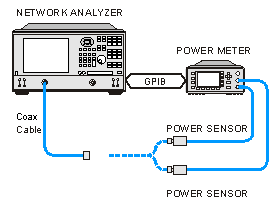
Connect coax cable, GPIB cable, and power sensors to the VNA as shown in graphic below.
This image does NOT apply to USB power sensors, which are connected directly to a VNA USB port.
See Important First-time USB connection note.
Note [M9808A, P50x8A/B] An external filter is required above 45 GHz to reduce sub-harmonics. See the power calibration at 45 GHz and above.
-
Apply power to the power meter and allow 30 minutes warm-up time before beginning calibration.
-
Select Source Power Cal as follows:
|
|
Using Hardkey/SoftTab/Softkey
|
-
Press Cal > Main > Other Cals > Source Power Cal....
|
|
Programming Commands
|
-
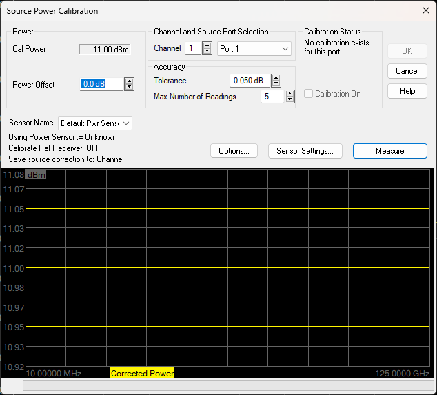
Complete the Source Power Cal dialog box (below), including Options, Loss Compensation and Configure Power Sensor, as needed.
Note: When using a Keysight N848X power sensor (sensors that do NOT have built-in calibration factors), enter the Cal Factors using the Configure Power Sensor dialog, because the VNA instructs the power meter to NOT use the Cal Factor tables internal to the power meter.
-
When complete, click Take a Cal Sweep in the Source Power Cal dialog box.
-
Follow the prompts to connect the sensors as required.
-
At this time you can change the Source Port setting and perform a Source Power Cal on a different port.
-
When calibration is finished, click OK. Correction is then applied and turned ON for the relevant ports on the active channel.
-
Remove sensor.
-
SrcPwrCal is displayed in the status bar when Source Power Correction is applied to the Active Measurement.
-
Perform a S-parameter calibration, which would use the corrected stimulus power levels for the relevant ports.
|
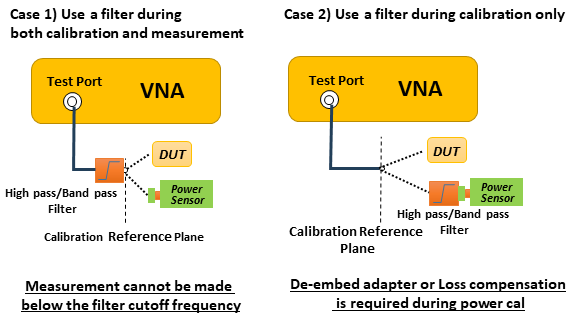
Power Calibration Setup at 45 GHz and above for M9808A, P50x8A/B/M, E5080B-xPx
When calibrating the power level at 45 GHz and above with a power sensor, a high pass filter or band pass filter (ex. Marki Microwave FH4000) is required at test port to reduce sub-harmonics. Otherwise, the power calibration cannot compensate the power level correctly due to sub harmonics. It is also recommended to use the filter during measurement, if DUT is sensitive to sub-harmonics level. (Case 1)
If the high pass filter is only used during power calibration, the insertion loss of the filter must be compensated by one of the following way (Case 2). The power calibration can be performed at several frequency segment as Use Multiple Sensors.
To turn Source Power Correction OFF:
-
On the Calibration menu,then click Source Power Correction on/OFF.
-
ONLY correction for the source port of the ACTIVE MEASUREMENT is turned OFF (regardless of port power coupling setting.)
|
Interpolation or Extrapolation
If the original stimulus settings are changed, Interpolation or EXTRAPOLATION is applied and SrcPwrCal* is displayed in the status bar. This is different from measurement calibration interpolation. For example, if the frequency span is increased, the VNA will extrapolate new correction values rather than turn correction off. This is to protect your test device from being overpowered by the source. If the original settings are restored, then source power calibration returns to full correction.
|
Source Power Cal dialog box help
|
|
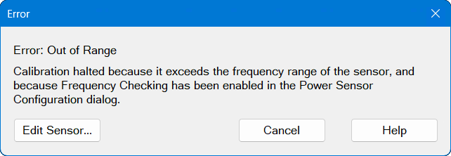
Note: Be sure that the frequency range of your power sensor covers the frequency range of your measurement. This does NOT occur automatically.
Cal with Frequency Extenders
If you are using a power sensor or power table to measure power over the frequency range of a frequency extender (mmWave module), the trace displays the measured power. This is done at the maximum RF input power setting for the frequency extender you are calibrating. This could be +10 dBm or +2 dBm depending on the power range you set during the source power calibration process. The default is +11 dBm to -30 dBm with a 0.5 db step size. This can be changed as needed.
Though the displayed frequency range is the range of the RF input, it is actually calibrating over the frequency range of the frequency extender being used. For example, the display shows 12.5 GHz to 18.333 GHz (RF input) but it is being calibrated from 75 GHz to 110 GHz.
Power
Cal Power The calculated power (in dBm) at the calibration point. This value is the specified VNA source power plus the Power Offset value.
Power Offset Allows you to specify a gain or loss (in dB) to account for components you connect between the source and the reference plane of your measurement. These components will remain during a measurement. For example, specify 10 dB to account for a 10 dB amplifier in the path to your DUT. Following the calibration, the VNA power readouts are adjusted to this value.
To account for components that will be removed when the calibration is complete, use the Loss Compensation table.
Channel and Port Selection
Channel Specifies the channel on which to perform the calibration. This setting defaults to the active channel.
Source Port Specifies the source port to be corrected. This setting defaults to the source port for the active measurement.
Note: External sources can be calibrated using this dialog. Learn more.
Accuracy
At each data point, power is measured using the specified Power Meter Settling Tolerance, then adjusted until the reading is within this Accuracy Tolerance or the Max Number of Readings has been met. The last power reading is plotted on the screen against the Tolerance limit lines.
Tolerance Sets the maximum desired deviation from the specified Cal Power level in 0.005 dB increments from 0 to 5 dB
Max Number of Readings Sets the maximum number of readings to take at each data point for iterating the source power. Enter a value between 1 and 1000.
Calibration Status
Allows you to turn Source Power Cal ON | OFF and view Cal data for each port, regardless of the active measurement. This feature allows the Internal Second Source to be calibrated and turned ON | OFF, even when being used as an incidental source in a measurement, such as an LO.
Calibration ON Check to turn Source Power Calibration ON for the specified source port.
The displayed text indicates when interpolation is applied for the calibration.
Buttons
Sensor Name All power sensors are displayed in this menu even if "Active - Show in UI" has been disabled in the External Devices setup dialog. You can select "Add Sensor..." to open the External Device Configuration dialog to the power meters page and configure more sensors. If you have pressed the "Options" button and selected "Receiver Only" or "Source Power Table", then this menu displays "None" and contains no entries.
Note: Default Sensor Auto-Switching. This feature is only available for Source Power Cal and SMC Smart Cal (GUI or SCPI) when the "Enable Frequency Checking" checkbox is selected. It automatically switches the sensor channel (A - B - C - D) when the calibration frequency is out of range for the current sensor channel's specified frequency range. See also, Enable Frequency Checking.
Options Invokes the Source Power Cal Options dialog. Label to the left of the button displays the current 'Options' setting.
Sensor Settings Opens the Configure Power Sensor dialog for the currently selected power sensor.
Measure Begins source power calibration measurement.
Frequency Checking Error Dialog:
If frequency checking has been enabled, then the VNA will check that the power sensors are defined over the calibration frequency range. If not, then this error dialog (see below) is displayed when you click the Measure button or, in the case of a Guided Power Calibration, the Next button.
Edit Sensor... Opens the "Configure Power Sensor" dialog for the selected sensor. The sensor I/O is connected automatically so the dialog displays all the settings and controls, rather than just showing the "Sensor Settings..." button. From this page, you can change the sensor settings. Clicking OK returns you directly to the Source Power Cal dialog.
Cancel Closes this dialog and returns you to the Source Power Cal dialog.
Calibration Warning Dialog:
If a power cal is going to be performed on a source which has the RF Pulse Modulator enabled, a warning dialog is displayed when you click Measure.
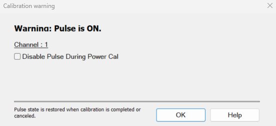
Disable Pulse During Power Cal Select the checkbox to disable the RF Pulse Modulator on the source being calibrated during the power cal only and will be re-enabled after the power cal.
For Noise Figure calibrations using a noise source, the Disable Pulse during Power Cal warning can be ignored.
If the channel is NFX with a controlled LO signal that is being modulated, and the LO is being power calibrated, the pulse warning should be considered.
OK Applies calibration. This button is disabled until the Take Cal Sweep has been pressed.
Cancel If a sweep is in progress, cancels the sweep. Press again to close the dialog.
Attention please: the power meter is operating in 200 r/s mode.
During a measurement, some Keysight power meters may display this message on the screen: It means that the meter is operating in 200 readings/sec which is the fastest speed setting for this meter. This is normal operation.
Pass / Fail Limits
Limit lines are drawn on the Source Power Cal measurement graticule area. These lines are at the Cal Power +/- the current setting of Accuracy Tolerance. A FAIL during the Source Power Cal sweep means that the VNA was unable to measure power to within the Accuracy Tolerance. Tight tolerances are more difficult to achieve at lower Cal Power levels. When a FAIL indication appears, increase the Max Number of Readings. If this does not cause a PASS condition, then decrease the Accuracy Tolerance value.
See Also
|
|
Source Power Calibration Options dialog box help
|
|
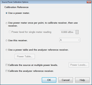
Provides options for measurement of the source power.
Note: At low power levels (less than -30 dBm) most power meters are not as accurate as a VNA receiver.
Calibration Reference Choose power meter/VNA receiver to use to measure power.
Note: Because the following two settings use VNA receivers to make power measurements, they do NOT work correctly when a Frequency Offset value is being used.
-
Use a power meter once, to calibrate receiver, then use receiver. When checked, the first reading at each data point uses a power meter to calibrate the reference receiver. Subsequent readings, if necessary to meet your accuracy requirement, are measured using the reference receiver. This technique is much faster than using the power meter, and more accurate when measuring low power levels.
Note: Do NOT use this setting if there is a component before the power sensor that exhibits non-linear behavior, such as a power amplifier in compression. Use a power meter and Calibrate the source at multiple power levels.
VNA receiver - For highest accuracy, first calibrate the receiver by performing a source power cal using a power meter, then a receiver cal. That receiver can then be used to quickly calibrate other VNA source ports, or used on another channel with different stimulus settings. This would be useful, for example, if the power level of the measurement was below the sensitivity of the power sensor. Calibrate the VNA receiver using a source power cal that is within the sensitivity of the sensor. Then, use the calibrated receiver to perform a second source power cal at the reduced power level.
-
-
The VNA receiver is specified using either standard receiver notation or logical receiver notation.
-
It is best to use the reference receiver for the source port to be calibrated. For example, if calibrating source port 2, specify "R2" or "a2" which is the same port 2 reference receiver using logical receiver notation.
-
To ensure an accurate source power cal, the frequency range over which the receiver was calibrated must be the same or larger than the "receiver only" source power calibration.
-
All accuracy and settling tolerance and number of reading settings apply just as they do with a power meter reading.
PMAR Device - The power meter/sensor must first be configured. Learn how to Configure a PMAR device.
Calibrate the source at multiple power levels Used primarily with mmWave measurements.
This feature can also be used with standard VNA measurements when a component is used in the source path such as a booster amp which does NOT have linear gain or loss over frequency. If this is not true for your setup but want to improve your source power accuracy, consider using the Receiver Leveling feature.
When checked, source power is measured using the specified 'Cal Reference' device (power meter/sensor or VNA receiver) and iterated on a sweep-to-sweep basis to construct a 2-dimensional power table: Power IN, Power OUT, over all frequencies.
-
Click Power Levels to launch the Source Cal Power Levels dialog box to set the power levels at which source power is to be measured.
-
The source power cal is saved, but the power table is NOT accessible.
Calibrate the analyzer reference receiver Check to calibrate the appropriate reference receiver to the power level that is measured at the calibration plane. Do this to make very accurate measurements using the calibrated reference receiver. This cal is done in addition to the standard source power cal using the any of the methods listed above. At the end of the source power cal measurement sweep, you can optionally save the reference receiver cal to a Cal Set to be recalled at a later time. The Cal is saved when the OK button is clicked to close the Source Power Cal dialog.
|
|
Source Cal Power Levels dialog box help
|
|
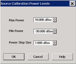
This dialog appears when you click Power Levels on the Source Power Cal Options dialog.
Specify the power levels at which the Source Power will be calibrated. These values should be set to a few dB more or less than the measurement power levels.
Max Power - The highest power level at which to calibrate. This value should be a few dB higher than the highest power level of your measurement.
Note: Setting the Max Power will override power settings entered manually in a Power Table (InputPower). Therefore, when using a power table, set the Max Power value to the same value shown in the Power Table (InputPower).
Min Power - The lowest power level at which to calibrate. This value should be a few dB lower than the lowest power level of your measurement.
Power Step - Calibrate at every incremental power level, between the Max and Min Power settings.
|
Copy a Source Power Calibration to other Channels
A macro application is now available that copies a Source Power Calibration to other channels. Once downloaded and installed on a VNA, the macro is automatically configured up. To learn more, click Help on the application main dialog.
Saving a Source Power Calibration
Because Source Power Cal calibrates source hardware, the calibration data is saved as part of the Instrument State in a .csa file only. This correction is applied to all measurements on the channel that uses the calibrated source. See Save Instrument State.
Reducing Time to Complete a Source Power Calibration
The time required to perform a Source Power Calibration depends on source power, number of points, and number of readings taken. You can reduce this measurement time with the following methods:
-
Reduce number of points before calibration. You can reduce the number of points before the measurement, then return the number of points to its original value after calibration is complete and correction is ON. The analyzer will perform a linear interpolation, although with some loss in accuracy.
-
Use an Keysight E-Series sensor. You can obtain 40+ readings per second over GPIB with this type of sensor on the VNA.
-
Increase power to the sensor. Lower power may have longer settling time with some sensors.
-
Check Use Reference Receiver for Iteration.
Receiver Power Calibration
Note: Source and Receiver Power Calibrations are NOT available in M937xA PXI.
Note: A Guided Power Cal can be performed during an S-parameter Guided Calibration. Learn more.
Receiver power calibration mathematically removes frequency response errors in the specified VNA receiver, and adjusts readings to the same, or a value offset from, the source power calibration level. It is the same as doing a Response Cal or Data / Memory, (Normalization) but with the data shifted to the Cal Power value.
Use Receiver Power Calibration to make very accurate absolute power (amplitude) measurements.
Receiver Power Calibration:
-
Is ONLY allowed when making absolute power (unratioed) measurements.
-
Is most accurate when a source power calibration was performed first.
-
Applies to all unratioed measurements in the active channel using that receiver.
-
Can be saved in a Cal Set and later reapplied to a like measurement.
Interpolation
Like other calibration types, if the original stimulus settings are narrowed, interpolation is applied and C* Rcvr Pwr is displayed in the status bar. If the original stimulus settings are made wider, the VNA will turn Receiver Power Correction OFF.
If the original settings are restored, then receiver power calibration returns to full correction.
How to perform a Receiver Power Calibration
-
Perform a Source Power Calibration.
-
Set the active measurement to unratioed. Learn How.
-
Connect a THRU line from the source port to the receiver port.
-
When performing a receiver power cal on a reference receiver (source 1 and receiver R1), no connection is necessary as the receiver is internally connected to the source.
-
When the source port and receiver port are the same (receiver A, source port 1), then connect an open or short to get maximum power to the receiver. This practice is not recommended. It is best to use different ports for the source and receiver.
-
Ensure correction for Source Power Calibration is ON as indicated by Src Pwr Cal or Src Pwr Cal* in the status bar.
-
Start the Calibration Wizard
|
|
Using Hardkey/SoftTab/Softkey
|
-
Set the active measurement to unratioed. Learn How.
-
Press Cal > Main > Other Cals > Receiver Power Cal....
|
|
Programming Commands
|
|
Select Calibration Type for Unratioed Measurement dialog box help
|
|
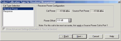
Cal Type Selection Select Receiver Power
Receiver Power Configuration
Cal Power Specifies the power level to be displayed on the measurement when complete. (Source Port Power + Power Offset).
Source Port Power Test port Power set for the measurement. Learn how to change Test Port Power
Power Offset Allows you to specify a gain or loss (in dB) to account for components you connect between the source and the reference plane of your measurement AFTER a source power cal has been performed. Following the calibration, the VNA power readouts are adjusted to the Cal Power value.
Next Click to continue the Calibration Wizard.
Notes:
-
When Receiver Power Cal is finished, 'Response' is displayed in the status bar and correction data is applied to subsequent sweeps. This is done because Receiver Power Cals are essentially Response Cals once they are stored and applied. See Saving a Receiver Power Cal below.
-
To turn correction OFF, click Cal > Main > Correction > Channel Correction OFF.
Learn more about Receiver Power Cal (scroll up).
|
Saving a Receiver Power Calibration
Beginning with VNA Revision 5.0, Receiver Power Cal is saved to a Cal Register and optionally to a User Cal Set. It can be applied to measurements in the same way as other Cal Types. Previously, Receiver Power Cal data was saved as part of an Instrument State and was only applied to the measurement on which it was performed.
Learn more about Saving VNA files types.