Operating Mode
The test set supports the following operating modes:
Active Cell Operating Mode
TD-SCDMA Test Operating Mode
CW Operating Mode
Cell Off Operating Mode
Active Cell Operating Mode
The Active Cell Operating Mode allows you to make a signalling connection between the test set (emulating a base station (BS) in a network) and a UE (mobile station). When connected (and during the connection process for some measurements), the UE's performance can be measured using the suite of measurements shown when the Measurement Selection key or Instrument Selection key is pressed.
You can configure the test set's base station emulator using the parameters described in Call Processing. While operating in Active Cell mode the test set is capable of performing many call processing operations.
|

|
Many of the settings used in active cell mode cannot be changed during active cell mode operation. A message is displayed to alert you to this situation if you try to change them. These are settings that must be set before attempting to get the UE connected on a call, or settings that are not normally changed during base station operation in a network. Use the Cell Off Operating Mode to change these settings.
|
Supported Downlink Channel in Active Cell Mode
The test set supports the following WCDMA downlink physical channels when operating in Active Cell operating mode:
-
DwPCH - Downlink Pilot Channel
-
P-CCPCH - Primary Common Control Physical Channel
-
DPCH - Dedicated Physical Channel
-
PICH - Paging Indicator Channel
-
DPCHo - Orthogonal Channel Noise Source
-
AWGN - Additive White Gaussian Noise
-
S-CCPCH - Secondary Common Control Physical Channel
-
FPACH – Fast Physical Access Channel
In addition, for HSDPA, the test set support the following HSDPA downlink channels:
Expected Uplink Channel in Active Cell Mode
The test set supports the following uplink physical channels when operating in Active Cell operating mode:
-
DPCH - Dedicated Physical Channel
-
UpPCH - Uplink Pilot Channel
-
PRACH – Physical Random Access Channel
In addition, for HSDPA, the test set support the following HSDPA uplink channels:
TD-SCDMA Test Operating Mode
When in TD-SCDMA Test Mode, the test set emulates a subset of the layer 1 functionalities of a TD-SCDMA Node B without sending any signalling information on the downlink channel. Changes to the UE configuration must be accomplished by directly sending commands to the UE from a system controller (usually a personal computer) through a proprietary digital interface.
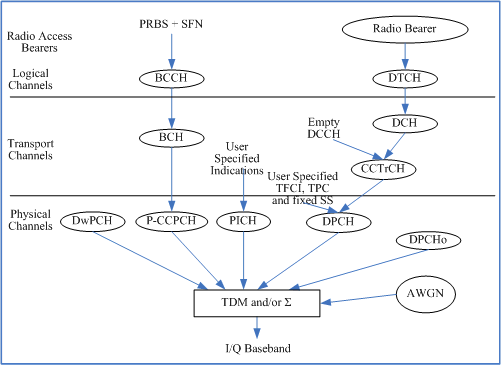
Upon entry into the TD-SCDMA Test Mode, the test set begins continuously transmitting a downlink signal consisting of the DwPCH, P-CCPCH, PICH and DPCH, along with DPCHo and AWGN sources if desired. The downlink DPCH configured for the bearer service is determined by Channel Type. The UE is expected to synchronize to the downlink channels and begin the transmission of an uplink DPCH configured to the same channel type as the downlink DPCH. The test set does not send any signaling message, except BCH messages, in TD-SCDMA Test mode.
Supported Downlink Channel in TD-SCDMA Test Mode
The test set supports the following downlink physical channels in TD-SCDMA Test mode. See Figure 1: Downlink Channels in TD-SCDMA Test Mode.
-
DwPCH - Downlink Pilot Channel
-
P-CCPCH - Primary Common Control Physical Channel
-
DPCH - Dedicated Physical Channel
-
PICH - Paging Indicator Channel
-
DPCHo - Orthogonal Channel Noise Source
-
AWGN - Additive White Gaussian Noise
Figure 1: Downlink Channels in TD-SCDMA Test Mode

There are two types of transport channels in the Downlink: Dedicated Channels (DCH) and Broadcast Channel (BCH).
Since the test set only supports TD-SCDMA Test operating mode with no signalling, the DCH used for signalling is transmitted with no data.
Expected Uplink Channel in TD-SCDMA Test Mode
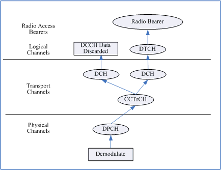
The test set only expects the uplink DPCH in TD-SCDMA Test mode. See Figure 2: Uplink Physical Channels.
Figure 2: Uplink Physical Channels

There are two DCHs expected from the UE. One is for DCCHs and the other is for the RMC DTCH.
When performing Loopback Bit Error Ratio (BER) Measurement in TD-SCDMA test operating mode, you must set UE Loopback Type to the loopback type 1 (the test set does not signal the loopback type to the UE), or else the measurement will fail.
The following settings are only available to TD-SCDMA Test operating mode:
CW Operating Mode
When in CW operating mode, the test set operates like a signal generator. The basic features provided by CW operating mode are:
-
No over the air signaling is used. Therefore there is no synchronization between the mobile station and test set.
-
No demodulation or channel decoding is available.
-
No automatic receiver control is provided. Expected CW power, measurement receiver frequency, and uplink receiver frequency are available as manual settings only.
-
Manual receiver control settings made while using the CW operating mode can affect manual receiver settings made in other operating modes. When changing operating modes and using manual receiver settings, you should always verify that the manual receiver settings are correct for the new operating mode.
-
Any one of three test signals can be generated while analyzing another signal (at the same frequency or at a different frequency). No interaction exists between these controls.
-
All test set measurements are available while in CW operating mode. However, measurements requiring protocol triggering cannot be made. Immediate triggering should be used for most measurements because no overhead signaling is occurring. Protocol triggering will timeout or report an integrity indicator other than zero.
Test Signals Description
The test set in CW operating mode provides any one of three test signals: CW (no modulation), AM (fixed 56% amplitude modulation), and DSB-SC (dual side-band suppressed carrier). You can select any one of three signals with adjustable power level and frequency for output to the currently selected front panel RF connector.
-
With CW test signal selected (the default setting), the test set provides an unmodulated carrier. With either AM or DSB-SC test signal selected, the test set will modulate the signal as shown in Figure 3: AM and DSB-SC test signals.
-
For any of the test signals selected, the output power level is controlled by the Cell Power ( F7 ). The Cell Power refers to the power found in the entire signal including sidebands if applicable.
-
For any of the test signals selected, the frequency is adjusted by changing the RF Gen Freq ( F8 ).
-
With the CW or AM signal selected, the RF Gen Freq setting represents the center frequency of the signal (fc).
-
With the DSB-SC signal selected, the RF Gen Freq setting represents the frequency of the lower sideband signal (fL). The upper sideband (fh) is 20 kHz above the RF Gen Freq setting, that is fh = fL+20 kHz.
Figure 3: AM and DSB-SC test signals

Cell Off Operating Mode
Cell Off operating mode and Active Cell operating mode share the same settings. However, Cell Off mode allows you to change the parameters that cannot be changed during Active Cell operation but used for call processing, such as downlink and uplink channel number (UARFCN), reference measurement channel configuration (Channel Type), signalling radio bearer configuration, etc.
Use Cell Off operating mode to set up those downlink and uplink parameters before establishing a connection to the UE (mobile station). After making the settings, switch to Active Cell operating mode to begin generating the downlink signal.
|

|
No signal is generated by the test set during Cell Off operation, regardless of the Cell Power setting. All settings are deferred until the Active Cell operating mode or FDD Test operating mode is used.
|
Related Topics
GPIB Commands: CALL:OPERating
![]()


