How Do I Make a Code Domain Measurement?
- Measuring Code Domain
- Measuring 3GPP TS 34.121-1 (v8.10.0) 5.2C UE Relative Code Domain Power Accuracy for HS-DPCCH (lab application or feature-licensed test application only)
- Measuring 3GPP TS 34.121-1 (v8.10.0) 5.2D UE Relative Code Domain Power Accuracy for HS-DPCCH and E-DCH (lab application or feature-licensed test application only)
- Measuring 3GPP TS 34.121-1 (v8.10.0) s5.2E UE Relative Code Domain Power Accuracy for HS-DPCCH and E-DCH with 16QAM (lab application or feature-licensed test application only)
- Measuring 3GPP TS 34.121-1 (v8.10.0) s5.13.1AAA EVM and IQ origin offset for HS-DPCCH and E-DCH with 16 QAM (lab application or feature-licensed test application only)
- Measuring 3GPP TS 34.121-1 (v8.10.0) 5.13.2A Relative Code Domain Error with HS-DPCCH (lab application or feature-licensed test application only)
- Measuring 3GPP TS 34.121-1 (v8.10.0) 5.13.2B Relative Code Domain Error with HS-DPCCH and E-DCH (lab application or feature-licensed test application only)
- Measuring 3GPP TS 34.121-1 (v8.10.0) s5.13.2C Relative Code Domain Error for HS-DPCCH and E-DCH with 16QAM (lab application or feature-licensed test application only)
Measuring Code Domain
- Establish an
RB Test Modeconnection between the UE and test set (see How Do I Set Up a Call and Make a Connection? ). - Press the Measurement selection key.
- Select
Code Domain. - Select
Code Domain Setup( F1 ) and set the measurement parameters as needed. SelectClose Menu( F6 ). - Set
Cell Power( F7 ) as needed. - If
Trigger Armis set toSingle, you must press the START SINGLE key to begin the measurement. - Select
Axis Control( F2 ). Set the axis control parameters as needed. SelectReturn( F6 ). - Select
Marker( F3 ) to turn on the marker on the graphical display.
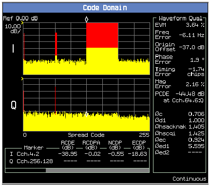
A typical result is shown below.
Measuring 3GPP TS 34.121-1 (v8.10.0) 5.2C UE Relative Code Domain Power Accuracy for HS-DPCCH
This section is applicable to the lab application or feature-licensed test application only.
- Set parameters that can only
be set in cell off operating mode (and other parameters
that are set from the same menu):
- Set
Operating Mode( F1 ) toCell Off. - Select
 34.121 Preset Call
							 Configurations
( F11 onCall Parms 1 of 3) and select5.2C,5.7A,5.13.1AA,5.13.2A:HSDPA:QPSK. You may then skip any steps marked with [34.121 Call Config] in this procedure. - Select
Channel (UARFCN) Parms( F12 onCall Parms 1 of 3). SetDL Channel( F7 ) to the appropriate "mid range" frequency for your UE's operating band, as specified by 3GPP TS 34.108 5.1.1 (for example, for operating band II setDL Channel=9800). - [34.121
Call Config] Select
Cell
Info (
F2 on
Call Control2 of 6 ). - [34.121
Call Config] Select
Cell
Parameters (
F2 ).
Set
Default
							 DPCH Offset
(DOFF) to3 x 512 chips. - [34.121 Call Config] Select
Uplink Parameters( F4 onCall Control 2 of 6).- [34.121
Call Config] Set
Uplink DPCH Bc/Bd ControltoManual. - [34.121 Call Config]
Set
Manual Uplink DPCH Bcto2(for 34.121-1 v8.10.0 Table C.10.1.4 sub-test 1). - [34.121 Call Config]
Set
Manual Uplink DPCH Bdto15(for 34.121-1 v8.10.0 Table C.10.1.4 sub-test 1). - [34.121 Call Config]
Set
Maximum Uplink Transmit Power Levelto+21 dBm.
- [34.121
Call Config] Set
- Set
Operating ModetoActive Cell(pressing the CALL SETUP key quickly brings you back to the top levelCall Controlmenu).
- Set
- Set
Cell Power( F7 onCall Parms 1 of 3) to-86 dBm/3.84 MHz. - [34.121 Call Config] Set
Channel Type( F8 ) to12.2k RMC + HSDPA. - [34.121 Call Config] Select
Generator Info( F3 onCall Control 2 of 6), selectDownlink Channel Levels(F3), selectConnected DL Channel Levels (F3 ), then selectHSDPA Conn DL Channel Levels( F4 ).- [34.121
Call Config] Set
HSDPA Cell 1 Connected CPICH Levelto-10 dB(this is the default value). - [34.121 Call Config] Set
HSDPA Cell 1 Connected P-CCPCH/SCH Levelto-12 dB(this is the default value). - [34.121 Call Config] Set
HSDPA Cell 1 Connected PICH Levelto-15 dB(this is the default value). - [34.121 Call Config] Set
HSDPA Cell 1 Connected DPCH Levelto-9 dB. - [34.121 Call Config] Set
HSDPA Cell 1 Connected HS-PDSCHs Level (Sum)to-3 dB(this is the default value). - [34.121 Call Config] Set
HSDPA Cell 1 Connected HS-SCCH 1 Levelto-8 dB.
- [34.121
Call Config] Set
- [34.121 Call Config] Select
HSDPA Parameters(HSPA Parameters( F10 ), F10 ).- [34.121 Call Config]
Select
 HSDPA
							 RB Test Mode Setup
( F8 ), then selectHSDPA RB Test Mode Settings( F8 ). - [34.121
Call Config] Set
RB Test HS-DSCH Configuration TypetoFRC(this is the default value). - [34.121 Call Config]
Set
FRC TypetoH-Set 1 QPSK(this is the default value). - [34.121
Call Config] Select
MAC-(e)hs Parameters( F10 ). - [34.121 Call Config] Select
HSDPA Uplink Parameters( F11 ).
- [34.121 Call Config]
Select
- Test
Application: Select
Cell
						 Parameters
( F2 ).
Lab Application: SelectCell Info( F2 ), thenCell Parameters( F2 ).
(from theCall Control 2 of 6menu) - Set
PS Domain InformationtoPresent(this is the default value in the lab application). - Qqualmin
and Qrxlevmin are fixed to -24 dB and -115
dBm, respectively, in the test application.
In the lab application these are the default
values for these parameters. They are accessible
from
Cell Info,Reselection Parameters( F3 ). - [34.121 Call Config] Select
RB Test Mode Setup( F6 onCall Control 3 of 6) and setUE Loopback TypetoType 1(this is the default value). - [34.121 Call Config] Select
UL CL Power Ctrl
							 Parameters
( F8 onCall Parms 3 of 3) and setUL CL Power Ctrl AlgorithmtoTwo(this is the default value). - Set
any other parameters needed to establish a connection
with your UE, then power on the UE and wait for
it to register (attach). See Establishing an HSDPA
Connection .
Note, before you can establish a connection in the PS domain (as is required for HSPA connections), the UE must attach to the test set. To enable this, thePS Domain Informationparameter must be set toPresentwhen the UE registers (attaches) with the test set. - Select
Originate Call( F3 onCall Control 1 of 6). - Drive
the UE to 0 dBm output power:
- Select
UL CL Power Ctrl Parameters( F8 onCall Parms 3 of 3) and setUL CL Power Ctrl ModetoActive bits (this is the default value). - Set
UE Target Power( F7 onCall Parms 3 of 3) to0 dBm. - Select
UL CL Power Ctrl Parameters( F8 onCall Parms 3 of 3). SetUL CL Power Ctrl ModetoAlternating bits.
- Select
- Press
the Measurement selection key
and select
Code Domain. - Select
Code Domain Setup( F1 ) . SetTrigger SourcetoHS-DPCCH. SetMeasurement Intervalto0.5 slot. - Measure
RCDPA for the following code domain measurement
configurations:
Measurement Points Measurement Point Subframe Alignment Slot Alignment Subslot Alignment 1 5 CQI2
0.5 2 0 ACKNACK
0 3 0 CQI1 0 4 1 ACKNACK 0 - If desired, show the NCDP
measurement result by selecting
Graph Control( F2 ) and setTable( F3 ) to2(so that you can compare the NCDP result with 3GPP TS 34.121-1 Table 5.2C.4).
- Use
the
Marker( F2 underGraph Control( F2 )) to ensure that the RCDPA result for each code channel meets the specified requirements in 34.121-1 Table 5.2C.3. The code channels are located as follows:Code Channels Code Channel Location Marker DPCCH Q Cch,256,0 0 DPDCH I Cch,64,16 64 HS-DPCCH Q Cch,256,64 64 - To
repeat this test for sub-tests 2-4:
- Perform
a Transport Channel Reconfiguration (
Handovers( F5 )) to change the following settings:Sub-test 2-4 Transport Channel Reconfiguration settings Setting Sub-test 2 Sub-test 3 Sub-test 4 TCR DPCH Bc/Bd Control Manual Manual Manual TCR Manual Uplink DPCH Bc 12
15 15 TCR Manual Uplink DPCH Bd 15 8
4 TCR DeltaACK, DeltaNACK 8 8 8 DeltaCQI 7 7 7 TCR Ack-Nack Repetition Factor 1 1 1 TCR CQI Feedback Cycle (k) 4 ms 4 ms 4 ms TCR CQI Repetition Factor 1 1 1 - Repeat steps 11 to 14.
- Perform
a Transport Channel Reconfiguration (
Measuring 3GPP TS 34.121-1 (v8.10.0) 5.2D UE Relative Code Domain Power Accuracy for HS-DPCCH and E-DCH
This section is applicable to the lab application or feature-licensed test application only.
- Set parameters that can only be
set in cell off operating mode (and other parameters
that are set from the same menu):
- Set
Operating Mode( F1 ) toCell Off. - Select
34.121 Preset Call Configurations( F11 onCall Parms 1 of 3) and select5.2D:HSPA:QPSK. You may then skip any steps marked with [34.121 Call Config] in this procedure. - Select
Channel (UARFCN) Parms( F12 onCall Parms 1 of 3). SetDL Channel( F7 ) to the appropriate "mid range" frequency for your UE's operating band, as specified by 3GPP TS 34.108 5.1.1 (for example, for operating band II setDL Channel=9800). - [34.121 Call Config] Select
Uplink Parameters( F4 onCall Control 2 of 6).- [34.121
Call Config] Set
Uplink DPCH Bc/Bd ControltoManual. - [34.121 Call Config] Set
Manual Uplink DPCH Bcto11(for 34.121-1 v8.10.0 Table C.11.1.3 sub-test 1). - [34.121 Call Config] Set
Manual Uplink DPCH Bdto15(for 34.121-1 v8.10.0 Table C.11.1.3 sub-test 1). - [34.121 Call Config] Set
Maximum Uplink Transmit Power Levelto+21 dBm.
- [34.121
Call Config] Set
- Set
Operating ModetoActive Cell(pressing the CALL SETUP key quickly brings you back to the top levelCall Controlmenu).
- Set
- Set
Cell Power( F7 onCall Parms 1 of 3) to-86 dBm/3.84 MHz. - [34.121 Call Config] Set
Channel Type( F8 ) to12.2k RMC + HSPA. - [34.121 Call Config] Select
Generator Info( F3 onCall Control 2 of 6), selectDownlink Channel Levels(F3), selectConnected DL Channel Levels (F3 ), then selectHSPA Conn DL Channel Levels( F4 ).- [34.121
Call Config] Set
HSPA Cell 1 Connected CPICH Levelto-10 dB(this is the default value). - [34.121 Call Config] Set
HSPA Cell 1 Connected P-CCPCH/SCH Levelto-12 dB(this is the default value). - [34.121 Call Config] Set
HSPA Cell 1 Connected PICH Levelto-15 dB(this is the default value). - [34.121 Call Config] Set
HSPA Cell 1 Connected (F-)DPCH Levelto-10 dB(this is the default value). - [34.121 Call Config] Set
HSPA Cell 1 Connected E-AGCH Levelto-20 dB(this is the default value). - [34.121 Call Config] Set
HSPA Cell 1 Connected E-HICH Levelto-20 dB(this is the default value). - [34.121 Call Config] Set
HSPA Cell 1 Connected E-RGCH LeveltoOff(this is the default value). - [34.121 Call Config] Set
HSPA Cell 1 Connected HS-PDSCHs Level (Sum)to-3 dB(this is the default value). - [34.121 Call Config] Set
HSPA Cell 1 Connected HS-SCCH 1 Levelto-8 dB.
- [34.121
Call Config] Set
- Select
HSUPA Parameters(HSPA Parameters( F10 ), F9 ).- [34.121
Call Config] Select
HSUPA RB Test Mode Setup( F8 ). - [34.121 Call Config] Select
Common HSUPA Parameters( F9 ).- [34.121
Call Config] Set
E-DPCCH/DPCCH Power Offset (DeltaE-DPCCH)to6(for 34.121-1 v8.10.0 Table C.11.1.3 sub-test 1). Note, 34.121-1 Table C.11.1.3 provides Beta ec (209/225 for sub-test 1). To determine what value of DeltaE-DPCCH corresponds to this, use 3GPP TS 25.213 Table 1B and the value of Beta c from 34.121-1 Table C.11.1.3 (11/15 for sub-test 1). For sub-test 1, A ec = Beta ec /Beta c = (209/225)/(11/15) = 19/15; therefore DeltaE-DPCCH = 6. - [34.121 Call Config] Set
Reference E-TFCI Power OffsetstoDefinition 34.121-01(for 34.121-1 v8.10.0 Table C.11.1.3 sub-test 1).
- [34.121
Call Config] Set
- Select
Serving Grant( F10 ).- [34.121
Call Config] Set
RB Setup AGto26: (119/15)^2(for34.121-1 v8.10.0 Table C.11.1.3 sub-test 1). Note, 34.121-1 Table C.11.1.3 AG Index corresponds to 3GPP TS 25.212 s4.10.1A.1 Table 16B, which maps the Absolute Grants sent on the E-AGCH. To send the equivalent Absolute Grant in the RB Setup message, you must use the AG Index in 3GPP TS 25.321 s9.2.5.2.1.1 Table 9.2.5.2.1.1. - Set
AG Mode( F7 ) toSingle Shot(this is the default value). - Select
AG Pattern Parameters( F11 ):
- [34.121
Call Config] Set
- [34.121
Call Config] Select
- [34.121 Call Config] Select
HSDPA Parameters(HSPA Parameters( F10 ), F10 ). - Test
Application: Select
Cell Parameters( F2 ).
Lab Application: SelectCell Info( F2 ), thenCell Parameters( F2 ).
(from theCall Control 2 of 6menu)- Set
PS Domain InformationtoPresent(this is the default value in the lab application). - Qqualmin
and Qrxlevmin are fixed to -24 dB and -115 dBm,
respectively, in the test application. In the
lab application these are the default values for
these parameters. They are accessible from
Cell Info,Reselection Parameters( F3 ).
- Set
- [34.121 Call Config] Select
RB Test Mode Setup( F6 onCall Control 3 of 6) and setUE Loopback TypetoType 1(this is the default value). - [34.121 Call Config] Select
UL CL Power Ctrl Parameters( F8 onCall Parms 3 of 3) and setUL CL Power Ctrl AlgorithmtoTwo(this is the default value). - Set
any other parameters needed to establish a connection
with your UE, then power on the UE and wait for it
to register (attach). See Establishing
an HSPA Connection .
Note, before you can establish a connection in the PS domain (as is required for HSPA connections), the UE must attach to the test set. To enable this, thePS Domain Informationparameter must be set toPresentwhen the UE registers (attaches) with the test set. - Select
Originate Call( F3 onCall Control 1 of 6). - Drive
the UE to 15 dBm +/- 2 dB output power:
- Select
UL CL Power Ctrl Parameters( F8 onCall Parms 3 of 3) and setUL CL Power Ctrl ModetoActive bits (this is the default value). - Set
UE Target Power( F7 onCall Parms 3 of 3) to1 dBm (for 34.121-1 v8.10.0 Table C.11.1.3 sub-test 1).This value is determined as follows:UE Target Poweronly sets the DPCCH+DPDCH power level of the UE. In order to achieve a total output power of +15 dBm +/-24 dB, you must setUE Target Powerto 15 dBm - Power change due to HS-DPCCH, E-DPCCH and E-DPDCH .
Power Change Due to HS-DPCCH, E-DPCCH and E-DPDCH = 10log 10 (Beta c ^2 + Beta d ^2 + Beta hs ^2 + Beta ec ^2 + Beta ed ^2) - 10log 10 (Beta d ^2 + Beta c ^2) = 14 dB for sub-test 1, so you must setUE Target Powerto 1 dBm for sub-test 1.
TheUE Target Powervalues for sub-tests 2-4 are as follows: sub-test 2: 10 dBm, sub-test 3: 2 dBm, sub-test 4: 13 dBm. - Select
Additional Screens( F1 fromCall Control 2 of 6), selectHSPA Information( F2 ) and observe the Last Received E-TFCI (it should be 75 for 34.121-1 v8.10.0 Table C.11.1.3 sub-test 1, 67 for sub-test 2, 92 for sub-test 3, and 71 for sub-test 4). If the E-TFCI value is not correct, fail the UE. Note that an E-TFCI of 75 corresponds to an uplink data rate of 2421 bits/10 ms = 242 kbps. The uplink data rate for sub-test 2 = 175 kbps, sub-test 3 = 483 kbps, and sub-test 4 = 206 kbps. - Select
UL CL Power Ctrl Parameters( F8 onCall Parms 3 of 3). SetUL CL Power Ctrl ModetoAlternating bits.
- Select
- Select
HSPA Parameters( F10 ),HSUPA Parameters( F9 ),Serving Grant( F10 ) and setAG Mode ( F7 )toPattern. - Press
the Measurement
selection key and select
Code Domain. - Select
Code Domain Setup( F1 ) and setTrigger SourcetoEven Frame. - Measure
RCDPA for the following code domain measurement configurations:
Measurement Points Measurement Point Timeslot SFN Alignment 1 14 Odd 2 0 Even 3 0 Odd - If desired, show the NCDP
measurement result by selecting
Graph Control( F2 ) and setTable( F3 ) to2(so that you can compare the NCDP result with 3GPP TS 34.121-1 table 5.2D.7).
- Use
the
Marker( F2 underGraph Control( F2 )) to ensure that the RCDPA result for each code channel meets the specified requirements in 34.121-1 table 5.2D.8. The code channels are located as follows:Code Channels Code Channel Location Marker DPCCH Q Cch,256,0 0 DPDCH I Cch,64,16 64 HS-DPCCH Q Cch,256,64 64 E-DPCCH I Cch,256,1 1 E-DPDCH1 I Cch,4,2 128 E-DPDCH2 Q Cch,4,2 128
- If desired, show the NCDP
measurement result by selecting
- To
repeat this test for sub-tests 2-4 (sub-test 5 is
not used with 34.121-1 V8.10.0 5.2D):
- Select
HSPA Parameters( F10 ),HSUPA Parameters( F9 ),Serving Grant( F10 ) and setAG Mode( F7 ) toSingle Shot. - Perform
a Transport Channel Reconfiguration (
Handovers( F5 )) to change the following settings:Sub-test 2-4 Transport Channel Reconfiguration settings Setting Sub-test 2 Sub-test 3 Sub-test 4 TCR DPCH Bc/Bd Control Manual Manual Manual TCR Manual Uplink DPCH Bc 6 15 2 TCR Manual Uplink DPCH Bd 15 9 15 TCR DeltaACK, DeltaNACK, DeltaCQI 8 8 8 TCR Ack-Nack Repetition Factor 3 3 3 TCR CQI Feedback Cycle (k) 4 ms 4 ms 4 ms TCR CQI Repetition Factor 2 2 2 TCR E-DPCCH/DPCCH Power Offset 8 8 5 TCR Reference E-TFCI Power Offsets 34121-01 34121-02 34121-01 TCR Absolute Grant 18: (47/15)^2 21: (67/15)^2 23: (84/15)^2 - Repeat step 12.
- Select
HSPA Parameters( F10 ),HSUPA Parameters( F9 ),Serving Grant( F10 ),AG Pattern Parameters( F11 ) and setAbsolute Grant Pattern - Value 1to12: (47/15)^2for sub-test 2,15: (67/15)^2for sub-test 3 and17: (84/15)^2for sub-test 4. - Set
AG Mode( F7 ) toPattern. - Repeat step 16.
- Select
Measuring 3GPP TS 34.121-1 (v8.10.0) s5.2E UE Relative Code Domain Power Accuracy for HS-DPCCH and E-DCH with 16QAM
This section is applicable to the lab application or feature-licensed test application only.
UE Relative Code Domain Power Accuracy for HS-DPCCH and E-DCH with 16QAM from 3GPP TS 34.121-1 s5.2E measures RCDPA on any release 7 or later UE that supports E-DCH category 7, 16QAM with HSUPA.
The test is performed with the UE transmitting at the maximum power.
- Set parameters that can only be
set in cell off operating mode (and other parameters
that are set from the same menu):
- Set
Operating Mode( F1 ) toCell Off. - Select
34.121 Preset Call Configurations( F11 onCall Parms 1 of 3) and select5.2E:HSPA+:UL 16QAM. You may then skip any steps marked with [34.121 Call Config] in this procedure. - Select
Channel (UARFCN) Parms( F12 onCall Parms 1 of 3). SetDL Channel( F7 ) to the appropriate "mid range" frequency for your UE's operating band, as specified by 3GPP TS 34.108 s5.1.1 (for example, for operating band II set DL Channel = 9800 ). - [34.121 Call Config] Select
Uplink Parameters( F4 onCall Control 2 of 6).- [34.121
Call Config] Set
Uplink DPCH Bc/Bd ControltoManual. - [34.121 Call Config] Set
Manual Uplink DPCH Bcto15(for 34.121-1 v8.10.0 table C.11.1.4 sub-test 1). - [34.121 Call Config]
Manual Uplink DPCH Bdcan remain at its default value. 34.121-1 v8.10.0 table C.11.1.4 sub-test 1 requires Beta d set to zero. This is configured by selecting a DL channel type with no DPDCH. The value set here for Beta d is not used because no DL DPDCH is generated. - [34.121 Call Config]
Set
Maximum Uplink Transmit Power Levelto+21 dBm.
- [34.121
Call Config] Set
- Set
Operating ModetoActive Cell(pressing the CALL SETUP key quickly brings you back to the top levelCall Controlmenu).
- Set
- Set
Cell Power( F7 onCall Parms 1 of 3) to-86 dBm/3.84 MHz. - [34.121 Call Config] Set
Channel Type( F8 ) toHSPA. - [34.121 Call Config] Select
Generator Info( F3 onCall Control 2 of 6), selectDownlink Channel Levels( F3 ),Connected DL Channel Levels( F3 ), then selectHSPA Conn DL Channel Levels( F4 ).- [34.121
Call Config] Set
HSPA Cell 1 Connected CPICH Levelto-10dB (this is the default value). - [34.121 Call Config] Set
HSPA Cell 1 Connected P-CCPCH/SCH Levelto-12 dB(this is the default value). - [34.121 Call Config] Set
HSPA Cell 1 Connected PICH Levelto-15 dB(this is the default value). - [34.121 Call Config] Set
HSPA Cell 1 Connected (F-)DPCH Levelto-10 dB(this is the default value). - [34.121 Call Config] Set
HSPA Cell 1 Connected E-AGCH Levelto-20 dB(this is the default value). - [34.121 Call Config] Set
HSPA Cell 1 Connected E-HICH Levelto-20 dB(this is the default value). - [34.121 Call Config] Set
HSPA Cell 1 Connected E-RGCH LeveltoOff(this is the default value). - [34.121 Call Config] Set
HSPA Cell 1 Connected HS-PDSCHs Level (Sum)to-3 dB(this is the default value). - [34.121 Call Config] Set
HSPA Cell 1 Connected HS-SCCH 1 Levelto-8 dB.
- [34.121
Call Config] Set
- [34.121 Call Config] Select
Generator Info( F3 onCall Control 2 of 6), selectDownlink Channel Configs( F4 ), and then selectHS-SCCH Configs( F3 ). - [34.121 Call Config] Select
HSUPA Parameters(HSPA Parameters( F10 ), F9 ).- [34.121
Call Config] Select
HSUPA RB Test Mode Setup( F8 ). - [34.121 Call Config] Select
Common HSUPA Parameters( F9 ).- [34.121
Call Config] Set
E-DCH TTIto2 ms. - [34.121 Call Config]
Set
E-DCH 16QAM StatetoOn. - [34.121 Call Config]
Set
E-DPCCH/DPCCH Power Offset (DeltaE-DPCCH)to8(for 34.121-1 v8.10.0 table C.11.1.4 sub-test 1). Note, 34.121-1 table C.11.1.4 provides Beta ec (30/15 for sub-test 1). To determine what value of DeltaE-DPCCH corresponds to this, use 3GPP TS 25.213 table 1B and the value of Beta c from 34.121-1 table C.11.1.4 (15/15 for sub-test 1). For sub-test 1, A ec = Beta ec /Beta c = (30/15)/(15/15) = 30/15; therefore DeltaE-DPCCH = 8. - [34.121 Call Config]
Set
E-TFCI Table Index (2 ms TTI with 16QAM)to2(this is the default value). - [34.121 Call Config]
Set
Reference E-TFCI Power Offset ControltoPredefined(this is the default value). - [34.121 Call Config]
Set
Reference E-TFCI Power OffsetstoDefinition 34.121-04(for 34.121-1 v8.10.0 table C.11.1.4 sub-test 1). - [34.121 Call Config]
Set
E-TFCI Boost Information StatetoOn. - [34.121 Call Config]
Set
E-TFCI Boost Valueto105. - [34.121 Call Config]
Set
DeltaT2TPto2(this is the default value). - [34.121 Call Config]
Set
BetaEd Gain E-AGCH Table Selectionto1(this is the default value). - [34.121 Call Config]
Set
E-DPDCH Power Calculation FormulatoExtrapolation(this is the default value).
- [34.121
Call Config] Set
- Select
Serving Grant( F10 ).- Set
AG Mode( F7 ) =Single Shot(this is the default value). - [34.121 Call Config]
Set
RB Setup AGto17: (75/15)^2(for 34.121-1 v8.10.0 table C.11.1.4 sub-test 1). Note, 34.121-1 table C.11.1.4 AG Index corresponds to 3GPP TS 25.212 s4.10.1A.1 table 16B.1, which maps the Absolute Grants sent on the E-AGCH. To send the equivalent Absolute Grant in the RB Setup message, you must use the AG Index in 3GPP TS 25.321 s9.2.5.2.1.1 table 9.2.5.2.1.2. - Select
AG Pattern Parameters( F8 ):
- Set
- [34.121
Call Config] Select
- [34.121 Call Config] Select
HSDPA Parameters(HSPA Parameters( F10 ), F10 ). - Test
Application: Select
Cell Parameters( F2 ).Lab Application: Select
Cell Info( F2 ), thenCell Parameters( F2 ) from theCall Control 2 of 6menu.- Set
PS Domain InformationtoPresent(this is the default value in the lab application). - Qqualmin
and Qrxlevmin are fixed to -24 dB and -115 dBm,
respectively, in the test application. In the
lab application these are the default values for
these parameters. They are accessible from
Cell Info,Reselection Parameters( F3 ).
- Set
- [34.121 Call Config] Select
RB Test Mode Setup( F6 onCall Control 3 of 6) and setUE Loopback TypetoType 1(this is the default value). - [34.121 Call Config] Select
UL CL Power Ctrl Parameters( F8 onCall Parms 3 of 3) and setUL CL Power Ctrl AlgorithmtoTwo(this is the default value). - Set any other parameters needed to establish a connection with your UE, then power on the UE and wait for it to register (attach).
- Select
Originate Call( F3 onCall Control 1 of 6). - Drive
the UE to maximum power:
- Select
UL CL Power Ctrl Parameters( F8 onCall Parms 3 of 3) and setUL CL Power Ctrl ModetoActive bits(this is the default value). - Set
UE Target Power( F7 onCall Parms 3 of 3) to3 dBm(for 34.121-1 v8.10.0 table C.11.1.4 sub-test 1, power class 3 UE). This value is determined as follows: Maximum power for a power class 3 UE is +24 dBm, but UE Target Power only sets the DPCCH+DPDCH power level of the UE. In order to achieve a total output power of +16.5 dBm (24 dBm - 7.5 dB as required in 34.121-1 s5.2B.4.2), you must set UE Target Power to at most 16.5 dBm - Power change due to HS-DPCCH, E-DPCCH and E DPDCH.Power Change Due to HS-DPCCH, E-DPCCH and E-DPDCH = 10log 10 (Beta c ^2 + Beta d ^2 + Beta hs ^2 + Beta ec ^2 + Beta ed1 ^2 + Beta ed2 ^2 + Beta ed3 ^2 + Beta ed4 ^2) - 10log 10 (Beta d ^2 + Beta c ^2) = 13.4 dB for sub-test 1, so you must set UE Target Power to 3 dBm for sub-test 1.
- Wait 150 ms.
- Press
the Measurement selection key and select
Channel Power. - Set up the measurement:
- Observe Channel Power to ensure that the UE's output power is at least 7.5 dB below maximum power (<16.5 dBm for power class 3 UEs).
- Select
UL CL Power Ctrl Parameters( F8 onCall Parms 3 of 3). SetUL CL Power Ctrl ModetoAlternating bits. - Select
Additional Screens( F1 fromCall Control 2 of 6), selectHSPA Information( F2 ) and observe theLast Received E-TFCI(it should be 105 for 34.121-1 v8.10.0 table C.11.1.4 sub-test 1). - Select
E-TFCI Recording Information( F3 ). - Select
HSPA Parameters( F10 ),HSUPA Parameters( F9 ),E-TFCI Recording( F11 ),E-TFCI Recording Parameters( F7 ).- [34.121
Call Config] Set
E-TFCI Recording Countto15(this is the default value). - Set
E-TFCI Recording BehaviortoAll. - Select
Send Step Up TPC Bit Pattern( F10 ) and thenStart Recording E-TFCI Values( F8 ). - Observe whether the UE sent any decreased E-TFCI. If not, send another up TPC bit and record E TFCI. Repeat until the UE sends at least one decreased E TFCI.
- Select
Send Step Down TPC Bit Pattern( F11 ) and thenStart Recording E-TFCI Values( F8 ). - Observe whether the UE sent any decreased E-TFCI. If it did, then send another down TPC bit, then continue to the next step. If not, continue to the next step.
- Confirm that the E-TFCI is equal to the target E-TFCI of 105 for sub-test 1. If not, fail the UE. Note that an E TFCI of 105 corresponds to a transport block size of 9185 bits (3GPP TS 25.321 table B.2a). The corresponding uplink data rate is 9185 bits/2 ms = 4.59 Mbps.
- [34.121
Call Config] Set
- Select
- Select
HSPA Parameters( F10 ),HSUPA Parameters( F9 ),Serving Grant( F10 ) and setAG ModetoPattern( F7 ). - Press
the Measurement selection key and select Code Domain.
- Select
Code Domain Setup( F1 ). - Measure
RCDPA for the following code domain measurement
configurations:
Measurement Points Measurement Point Timeslot SFN Alignment 1 14 Odd 2 0 Even 3 0 Odd - If
desired, show NCDP by selecting
Graph Control( F2 ) and settingTable( F3 ) =2so that you can compare NCDP with 3GPP TS 34.121 table 5.2D.7. - Use
the Marker ( F2 under
Graph Control( F2 ) ) to ensure that RCDPA for each code channel meets the specified requirements in 34.121-1 table 5.2E.6. The code channels are located as follows (as defined in 3GPP TS 25.213):Code Channels Code Channel Location Marker DPCCH Q Cch,256,0 0 E-DPCCH I Cch,256,1 1 E-DPDCH1 I Cch,2,1 128 E-DPDCH2 Q Cch,2,1 128 E-DPDCH3 I Cch,4,1 64 E-DPDCH4 Q Cch,4,1 64
- Select
Measuring 3GPP TS 34.121-1 (v8.10.0) s5.13.1AAA EVM and IQ origin offset for HS-DPCCH and E-DCH with 16 QAM
This section is applicable to the lab application or feature-licensed test application only.
EVM and IQ Origin Offset for H-DPCCH and E-DCH with 16QAM from 3GPP TS 34.121-1 s5.13.1AAA measures EVM and IQ origin offset power on any release 7 or later UE that supports E-DCH category 7, 16QAM with HSUPA.
The test is performed with the UE transmitting at -28 dBm.
- Set parameters that can only be
set in cell off operating mode (and other parameters
that are set from the same menu):
- Set
Operating Mode( F1 ) toCell Off. - Select
34.121 Preset Call Configurations( F11 onCall Parms 1 of 3) and select5.13.1AAA, 5.13.2C:HSPA+:UL 16QAM. You may then skip any steps marked with [34.121 Call Config] in this procedure. - Select
Channel (UARFCN) Parms( F12 onCall Parms 1 of 3). SetDL Channel( F7 ) andUplink Channel( F8 ) to the appropriate "low range" frequencies for your UE's operating band, as specified by 3GPP TS 34.108 s5.1.1 (for example, for operating band II, set DL Channel = 9663 ). - [34.121 Call Config] Select
Uplink Parameters( F4 onCall Control 2 of 6).- [34.121
Call Config] Set
Uplink DPCH Bc/Bd ControltoManual. - [34.121 Call Config]
Set
Manual Uplink DPCH Bcto15(for 34.121-1 v8.10.0 table C.11.1.4 sub-test 1). - [34.121 Call Config]
Manual Uplink DPCH Bdcan remain at its default value. 34.121-1 v8.10.0 table C.11.1.4 sub-test 1 requires Beta d set to zero. This is configured by selecting a DL channel type with no DPDCH. The value set here for Beta d is not used because no DL DPDCH is generated. - [34.121 Call Config]
Set
Maximum Uplink Transmit Power Levelto+21 dBm.
- [34.121
Call Config] Set
- Set
Operating ModetoActive Cell(pressing the CALL SETUP key quickly brings you back to the top levelCall Controlmenu).
- Set
- Set
Cell Power( F7 onCall Parms 1 of 3) to-86 dBm/3.84 MHz. - [34.121 Call Config] Set
Channel Type( F8 ) toHSPA. - [34.121 Call Config] Select
Generator Info( F3 onCall Control 2 of 6), selectDownlink Channel Levels( F3 ),Connected DL Channel Levels( F3 ), then selectHSPA Conn DL Channel Levels( F4 ).- [34.121
Call Config] Set
HSPA Cell 1 Connected CPICH Levelto-10 dB(this is the default value). - [34.121 Call Config] Set
HSPA Cell 1 Connected P-CCPCH/SCH Levelto-12 dB(this is the default value). - [34.121 Call Config] Set
HSPA Cell 1 Connected PICH Levelto-15 dB(this is the default value). - [34.121 Call Config] Set
HSPA Cell 1 Connected (F-)DPCH Levelto-10 dB(this is the default value). - [34.121 Call Config] Set
HSPA Cell 1 Connected E-AGCH Levelto-20 dB(this is the default value). - [34.121 Call Config] Set
HSPA Cell 1 Connected E-HICH Levelto-20 dB(this is the default value). - [34.121 Call Config] Set
HSPA Cell 1 Connected E-RGCH LeveltoOff(this is the default value). - [34.121 Call Config] Set
HSPA Cell 1 Connected HS-PDSCHs Level (Sum)to-3 dB(this is the default value). - [34.121 Call Config] Set
HSPA Cell 1 Connected HS-SCCH 1 Levelto-8 dB.
- [34.121
Call Config] Set
- [34.121 Call Config] Select
Generator Info( F3 onCall Control 2 of 6), selectDownlink Channel Configs( F4 ), and then selectHS-SCCH Configs( F3 ). - [34.121 Call Config] Select
HSUPA Parameters(HSPA Parameters( F10 ), F9 ).- [34.121
Call Config] Select
HSUPA RB Test Mode Setup( F8 ). - [34.121 Call Config] Select
Common HSUPA Parameters( F9 ).- [34.121
Call Config] Set
E-DCH TTIto2 ms. - [34.121 Call Config]
Set
E-DCH 16QAM StatetoOn. - [34.121 Call Config]
Set
E-DPCCH/DPCCH Power Offset (DeltaE-DPCCH)to8(for 34.121-1 v8.10.0 table C.11.1.4 sub-test 1). Note, 34.121-1 table C.11.1.4 provides Beta ec (30/15 for sub-test 1). To determine what value of DeltaE-DPCCH corresponds to this, use 3GPP TS 25.213 table 1B and the value of Beta c from 34.121-1 table C.11.1.4 (15/15 for sub-test 1). For sub-test 1, A ec = Beta ec /Beta c = (30/15)/(15/15) = 30/15; therefore DeltaE-DPCCH = 8. - [34.121 Call Config]
Set
E-TFCI Table Index (2 ms TTI with 16QAM)to2(this is the default value). - [34.121 Call Config]
Set
Reference E-TFCI Power Offset ControltoPredefined(this is the default value). - [34.121 Call Config]
Set
Reference E-TFCI Power OffsetstoDefinition 34.121-04(for 34.121-1 v8.10.0 table C.11.1.4 sub-test 1). 34.121-1 v8.10.0 table 5.2E.2 is used for this configuration; however, this table is identical to 34.121-1 table 5.13.1AAA.3. - [34.121 Call Config] Set
E-TFCI Boost Information StatetoOn. - [34.121 Call Config]
Set
E-TFCI Boost Valueto105. - [34.121 Call Config]
Set
DeltaT2TPto2(this is the default value). - [34.121 Call Config]
Set
BetaEd Gain E-AGCH Table Selectionto1(this is the default value). - [34.121 Call Config] Set
E-DPDCH Power Calculation FormulatoExtrapolation(this is the default value).
- [34.121
Call Config] Set
- [34.121 Call Config] Select
Serving Grant( F10 ).- [34.121
Call Config] Set
AG ModetoSingle Shot(this is the default value). - [34.121 Call Config]
Set
Single Shot AGto14: (75/15)^2(for 34.121-1 v8.10.0 table C.11.1.4 sub-test 1). - [34.121 Call Config]
Set
RB Setup AGto17: (75/15)^2(for 34.121-1 v8.10.0 table C.11.1.4 sub-test 1). Note, 34.121-1 table C.11.1.4 AG Index corresponds to 3GPP TS 25.212 s4.10.1A.1 table 16B.1, which maps the Absolute Grants sent on the E-AGCH. To send the equivalent Absolute Grant in the RB Setup message, you must use the AG Index in 3GPP TS 25.321 s9.2.5.2.1.1 table 9.2.5.2.1.2.
- [34.121
Call Config] Set
- [34.121
Call Config] Select
- [34.121 Call Config] Select
HSDPA Parameters(HSPA Parameters( F10 ), F10 ). - Test
Application: Select
Cell
					 Parameters
( F2 ).Lab Application: Select
Cell Info( F2 ), thenCell Parameters( F2 ) from theCall Control 2 of 6menu.- Set
PS Domain InformationtoPresent(this is the default value in the lab application). - Qqualmin and Qrxlevmin are fixed to -24 dB and -115 dBm, respectively, in the test application. In the lab application these are the default values for these parameters. They are accessible from Cell Info , Reselection Parameters ( F3 ).
- Set
- [34.121 Call Config] Select
RB Test Mode Setup( F6 onCall Control 3 of 6) and setUE Loopback TypetoType 1(this is the default value). - [34.121 Call Config] Select
UL CL Power Ctrl
						 Parameters
( F8 onCall Parms 3 of 3) and setUL CL Power Ctrl AlgorithmtoTwo(this is the default value). - Set any other parameters needed to establish a connection with your UE, then power on the UE and wait for it to register (attach).
- Select
Originate Call( F3 onCall Control 1 of 6). - Select
UL CL Power Ctrl Parameters( F8 onCall Parms 3 of 3) and setUL CL Power Ctrl ModetoActive bits(this is the default value). - Set
UE Target Power( F7 onCall Parms 3 of 3) to -41 dBm. This value is determined as follows: 34.121-1 s5.13.1AAA requires a UE output power of -28 dBm ± 2 dB, but UE Target Power only sets the DPCCH+DPDCH power level of the UE. In order to achieve a total output power of -28 dBm, you must set UE Target Power to at most -28 dBm - Power change due to HS-DPCCH, E-DPCCH and E-DPDCH.Power Change Due to HS-DPCCH, E-DPCCH and E-DPDCH = 10log 10 (Beta c ^2 + Beta d ^2 + Beta hs ^2 + Beta ec ^2 + Beta ed1 ^2 + Beta ed2 ^2 + Beta ed3 ^2 + Beta ed4 ^2) - 10log 10 (Beta d ^2 + Beta c ^2) = 13.4 dB for sub-test 1, so you must set UE Target Power to -41 dBm. - Select
UL CL Power Ctrl Parameters( F8 onCall Parms 3 of 3) and setUL CL Power Ctrl ModetoAlternating bits. - Press
the Measurement selection key and select
Code Domain. - To
repeat the test case at "mid range" and
"high range" frequencies, use
Physical Channel Reconfig( F5 onCall Control 1 of 6, F1 ) to perform a hard handover to the next channel. Set theHandover Downlink Channel (UARFCN)andHandover Uplink Channel (UARFCN)parameters to the appropriate "mid range" or "high range" frequencies for your UE's operating band, as specified by 3GPP TS 34.108 s5.1.1.Execute Handover( F5 ) and then repeat steps 13 through 16.
Measuring 3GPP TS 34.121-1 (v8.10.0) 5.13.2A Relative Code Domain Error with HS-DPCCH
This section is applicable to the lab application or feature-licensed test application only.
- Set parameters that can only be
set in cell off operating mode (and other parameters
that are set from the same menu):
- Set
Operating Mode( F1 ) toCell Off. - Select
34.121 Preset Call Configurations( F11 onCall Parms 1 of 3) and select5.2C, 5.7A, 5.13.1A, 5.13.1AA, and 5.13.2A:HSDPA:QPSK, then select the desired sub-test. You may then skip any steps marked with [34.121 Call Config] in this procedure. - Select
Channel (UARFCN) Parms( F12 onCall Parms 1 of 3). SetDL Channel( F7 ) to the appropriate "low range" frequency for your UE's operating band, as specified by 3GPP TS 34.108 5.1.1 (for example, for operating band II setDL Channel=9663). - [34.121
Call Config] Select
Cell Info( F2 onCall Control 2 of 6). - [34.121
Call Config] Select
Cell Parameters( F2 ). SetDefault DPCH Offset (DOFF)to3 x 512 chips. - [34.121 Call Config] Select
Uplink Parameters( F4 onCall Control 2 of 6).- [34.121
Call Config] Set
Uplink DPCH Bc/Bd ControltoManual. - [34.121 Call Config] Set
Manual Uplink DPCH Bcto2(for 34.121-1 v8.10.0 Table C.10.1.4 sub-test 1). - [34.121 Call Config] Set
Manual Uplink DPCH Bdto15(for 34.121-1 v8.10.0 Table C.10.1.4 sub-test 1). - [34.121 Call Config] Set
Maximum Uplink Transmit Power Levelto+21 dBm.
- [34.121
Call Config] Set
- Set
Operating ModetoActive Cell(pressing the CALL SETUP key quickly brings you back to the top levelCall Controlmenu).
- Set
- Set
Cell Power( F7 onCall Parms 1 of 3) to-86 dBm/3.84 MHz. - [34.121 Call Config] Set
Channel Type( F8 ) to12.2k RMC + HSDPA. - [34.121 Call Config] Select
Generator Info( F3 onCall Control 2 of 6), selectDownlink Channel Levels( F3 ), selectConnected DL Channel Levels( F3 ), then selectHSDPA Conn DL Channel Levels( F4 ).- [34.121
Call Config] Set
HSDPA Cell 1 Connected CPICH Levelto-10 dB(this is the default value). - [34.121 Call Config] Set
HSDPA Cell 1 Connected P-CCPCH/SCH Levelto-12 dB(this is the default value). - [34.121 Call Config] Set
HSDPA Cell 1 Connected PICH Levelto-15 dB(this is the default value). - [34.121 Call Config] Set
HSDPA Cell 1 Connected DPCH Levelto-9 dB. - [34.121 Call Config] Set
HSDPA Cell 1 Connected HS-PDSCHs Level (Sum)to-3 dB(this is the default value). - [34.121 Call Config] Set
HSDPA Cell 1 Connected HS-SCCH 1 Levelto-8 dB.
- [34.121
Call Config] Set
- [34.121 Call
Config] Select
HSDPA Parameters(HSPA Parameters( F10 ), F10 ). - [34.121
Call Config] Select
HSDPA RB Test Mode Setup( F8 ), then selectHSDPA RB Test Mode Settings( F8 ). - [34.121
Call Config] Select
MAC-(e)hs Parameters( F10 ). - [34.121 Call Config] Select
HSDPA Uplink Parameters( F11 ). - Test
Application: Select
Cell Parameters( F2 ).
Lab Application: SelectCell Info( F2 ), thenCell Parameters( F2 ).
( from theCall Control 2 of 6menu)- Set
PS Domain InformationtoPresent(this is the default value in the lab application). - Qqualmin
and Qrxlevmin are fixed to -24 dB and -115 dBm,
respectively, in the test application. In the
lab application these are the default values for
these parameters. They are accessible from
Cell Info,Reselection Parameters( F3 ).
- Set
- [34.121 Call Config] Select
RB Test Mode Setup( F6 onCall Control 3 of 6) and setUE Loopback TypetoType 1(this is the default value). - [34.121 Call Config] Select
UL CL Power Ctrl Parameters( F8 onCall Parms 3 of 3) and setUL CL Power Ctrl AlgorithmtoTwo(this is the default value). - Set
any other parameters needed to establish a connection
with your UE, then power on the UE and wait for it
to register (attach). See Establishing an HSDPA Connection
.
Note, before you can establish a connection in the PS domain (as is required for HSPA connections), the UE must attach to the test set. To enable this, thePS Domain Informationparameter must be set toPresentwhen the UE registers (attaches) with the test set. - Select
Originate Call( F3 onCall Control 1 of 6). - Drive
the UE to maximum output power:
- Set
UE Target Power( F7 onCall Parms 3 of 3) to a high value, such as 24dBm.The test set drives the UE to the specified level (or simply continues to send all up bits if the UE does not reach that level), while also appropriately ranging the test set's measurement receiver. - Select
UL CL Power Ctrl Parameters( F8 onCall Parms 3 of 3) and setUL CL Power Ctrl ModetoAll Up bits.
- Set
- Press
the Measurement selection key
and select
Code Domain. - Select Code Domain Setup ( F1).
- Measure RCDE:
- Show the NCDP and ECDP measurement
results by selecting
Graph Control( F2 ) and setTable( F3 ) to2(so that you can compare the NCDP and ECDP results with 3GPP TS 34.121-1 Table 5.13.2A.4). - Use the
Marker( F2 underGraph Control( F2 )) to ensure that the RCDE result for each code channel meets the specified requirements in 34.121-1 Table 5.13.2A.5. - The code channels are located
as follows:
Code Channels Code Channel Location Marker DPCCH Q Cch,256,0 0 DPDCH I Cch,64,16 64 HS-DPCCH Q Cch,256,64 64
- Show the NCDP and ECDP measurement
results by selecting
- To
repeat this test for sub-tests 3 and 4 (sub-test 2
is not required):
- Perform a Transport Channel
Reconfiguration (
Handovers( F5 )) to change the following settings:Sub-test 2-4 Transport Channel Reconfiguration settings Setting Sub-test 3 Sub-test 4 TCR DPCH Bc/Bd Control Manual Manual TCR Manual Uplink DPCH Bc 15 15
TCR Manual Uplink DPCH Bd 8 4
TCR DeltaACK and DeltaNACK 8 8 TCR DeltaCQI 7 7 TCR Ack-Nack Repetition Factor 1
1
TCR CQI Feedback Cycle (k) 4 ms 4 ms TCR CQI Repetition Factor 1
1 - Repeat step 14 (measure RCDE for each code channel).
- Perform a Transport Channel
Reconfiguration (
- Perform
a Transport Channel Reconfiguration (
Handovers( F5 )) to change the following settings:Sub-test 1 Transport Channel Reconfiguration settings Setting Sub-test 1 TCR DPCH Bc/Bd Control Manual TCR Manual Uplink DPCH Bc 2 TCR Manual Uplink DPCH Bd 15 TCR DeltaACK and DeltaNACK 8 TCR DeltaCQI 7 TCR Ack-Nack Repetition Factor 1 TCR CQI Feedback Cycle (k) 4 ms TCR CQI Repetition Factor 1 - Drive UE output power to -18 dBm:
- Repeat step 14 (measure RCDE for each code channel).
- To
repeat this test for sub-tests 3 and 4:
- Perform a Transport Channel
Reconfiguration (
Handovers( F5 )) to change the following settings:
Setting Sub-test 3 Sub-test 4 TCR DPCH Bc/Bd Control Manual Manual TCR Manual Uplink DPCH Bc 15 15
TCR Manual Uplink DPCH Bd 8 4
TCR DeltaACK and DeltaNACK 8 8 TCR DeltaCQI 7 7 TCR Ack-Nack Repetition Factor 1
1
TCR CQI Feedback Cycle (k) 4 ms 4 ms TCR CQI Repetition Factor 1
1 - Repeat step 17 (drive UE to -18 dBm) and step 14 (measure RCDE for each code channel).
- Perform a Transport Channel
Reconfiguration (
- Perform
a Physical Channel Reconfiguration (
Handovers( F5 )) to repeat the testing at mid- and high- range frequencies.
Measuring 3GPP TS 34.121-1 (v8.10.0) 5.13.2B Relative Code Domain Error with HS-DPCCH and E-DCH
This section is applicable to the lab application or feature-licensed test application only.
- Set parameters that can only be
set in cell off operating mode (and other parameters
that are set from the same menu):
- Set
Operating Mode( F1 ) toCell Off. - Select
34.121 Preset Call Configurations( F11 onCall Parms 1 of 3) and select5.2B, 5.9B, 5.10B, and 5.13.2B:HSPA:QPSK, then select the desired sub-test. You may then skip any steps marked with [34.121 Call Config] in this procedure. - Select
Channel (UARFCN) Parms( F12 onCall Parms 1 of 3). SetDL Channel( F7 ) to the appropriate "low range" frequency for your UE's operating band, as specified by 3GPP TS 34.108 5.1.1 (for example, for operating band II setDL Channel=9663). - [34.121 Call Config] Select
Uplink Parameters( F4 onCall Control 2 of 6).- [34.121
Call Config] Set
Uplink DPCH Bc/Bd ControltoManual. - [34.121 Call Config] Set
Manual Uplink DPCH Bcto11(for 34.121-1 v8.10.0 Table C.11.1.3 sub-test 1). - [34.121 Call Config] Set
Manual Uplink DPCH Bdto15(for 34.121-1 v8.10.0 Table C.11.1.3 sub-test 1). - [34.121 Call Config] Set
Maximum Uplink Transmit Power Levelto21 dBm.
- [34.121
Call Config] Set
- Set
Operating ModetoActive Cell(pressing the CALL SETUP key quickly brings you back to the top levelCall Controlmenu).
- Set
- Set
Cell Power( F7 onCall Parms 1 of 3) to-86 dBm/3.84 MHz. - [34.121 Call Config] Set
Channel Type( F8 ) to12.2k RMC + HSPA. - [34.121 Call Config] Select
Generator Info( F3 onCall Control 2 of 6), selectDownlink Channel Levels( F3 ), selectConnected DL Channel Levels( F3 ), then selectHSPA Conn DL Channel Levels( F4 ).- [34.121
Call Config] Set
HSPA Cell 1 Connected CPICH Levelto-10 dB(this is the default value). - [34.121 Call Config] Set
HSPA Cell 1 Connected P-CCPCH/SCH Levelto-12 dB(this is the default value). - [34.121 Call Config] Set
HSPA Cell 1 Connected PICH Levelto-15 dB(this is the default value). - [34.121 Call Config] Set
HSPA Cell 1 Connected (F-)DPCH Levelto-10 dB(this is the default value). - [34.121 Call Config] Set
HSPA Cell 1 Connected E-AGCH Levelto-20 dB(this is the default value). - [34.121 Call Config] Set
HSPA Cell 1 Connected E-HICH Levelto-20 dB(this is the default value). - [34.121 Call Config] Set
HSPA Cell 1 Connected E-RGCH LeveltoOff(this is the default value). - [34.121 Call Config] Set
HSPA Cell 1 Connected HS-PDSCHs Level (Sum)to-3 dB(this is the default value). - [34.121 Call Config] Set
HSPA Cell 1 Connected HS-SCCH 1 Levelto-8 dB.
- [34.121
Call Config] Set
- [34.121 Call Config] Select
HSUPA Parameters(HSPA Parameters( F10 ), F9 ).- [34.121
Call Config] Select
HSUPA RB Test Mode Setup( F8 ). - [34.121 Call Config] Select
Common HSUPA Parameters( F9 ).- [34.121
Call Config] Set
E-DPCCH/DPCCH Power Offset (DeltaE-DPCCH)to6(for 34.121-1 v8.10.0 Table C.11.1.3 sub-test 1). Note, 34.121-1 Table C.11.1.3 provides Beta ec (209/225 for sub-test 1). To determine what value of DeltaE-DPCCH corresponds to this, use 3GPP TS 25.213 Table 1B and the value of Beta c from 34.121-1 Table C.11.1.3 (11/15 for sub-test 1). For sub-test 1, A ec = Beta ec /Beta c = (209/225)/(11/15) = 19/15; therefore DeltaE-DPCCH = 6. - [34.121 Call Config] Set
Reference E-TFCI Power OffsetstoDefinition 34.121-01(for 34.121-1 v8.10.0 Table C.11.1.3 sub-test 1).
- [34.121
Call Config] Set
- [34.121 Call Config] Select
Serving Grant( F10 ).- [34.121
Call Config] Set
RB Setup AGto26: (119/15)^2(for 34.121-1 v8.10.0 Table C.11.1.3 sub-test 1). Note, 34.121-1 Table C.11.1.3 AG Index corresponds to 3GPP TS 25.212 s4.10.1A.1 Table 16B, which maps the Absolute Grants sent on the E-AGCH. To send the equivalent Absolute Grant in the RB Setup message, you must use the AG Index in 3GPP TS 25.321 s9.2.5.2.1.1 Table 9.2.5.2.1.1.
- [34.121
Call Config] Set
- [34.121
Call Config] Select
- [34.121 Call Config] Select
HSDPA Parameters(HSPA Parameters( F10 ), F10 ). - Test
Application: Select
Cell Parameters( F2 ).
Lab Application: SelectCell Info( F2 ), thenCell Parameters( F2 ).
( from theCall Control 2 of 6menu)- Set
PS Domain InformationtoPresent(this is the default value in the lab application). - Qqualmin
and Qrxlevmin are fixed to -24 dB and -115 dBm,
respectively, in the test application. In the
lab application these are the default values for
these parameters. They are accessible from
Cell Info,Reselection Parameters( F3 ).
- Set
- [34.121 Call Config] Select
RB Test Mode Setup( F6 onCall Control 3 of 6) and setUE Loopback TypetoType 1(this is the default value). - [34.121 Call Config] Select
UL CL Power Ctrl Parameters( F8 onCall Parms 3 of 3) and setUL CL Power Ctrl AlgorithmtoTwo(this is the default value). - Set
any other parameters needed to establish a connection
with your UE, then power on the UE and wait for it
to register (attach). See Establishing
an HSPA Connection .
Note, before you can establish a connection in the PS domain (as is required for HSPA connections), the UE must attach to the test set. To enable this, thePS Domain Informationparameter must be set toPresentwhen the UE registers (attaches) with the test set. - Select
Originate Call( F3 onCall Control 1 of 6). - Drive
the UE to 15 dBm +/- 2 dB output power:
- Select
UL CL Power Ctrl Parameters( F8 onCall Parms 3 of 3) and setUL CL Power Ctrl ModetoActive bits(this is the default value). - Set
UE Target Power( F7 onCall Parms 3 of 3) to1 dBm (for 34.121-1 v8.10.0 Table C.11.1.3 sub-test 1).This value is determined as follows:UE Target Poweronly sets the DPCCH+DPDCH power level of the UE. In order to achieve a total output power of +15 dBm, you must setUE Target Powerto at most 15 dBm - Power change due to HS-DPCCH, E-DPCCH and E-DPDCH .
Power Change Due to HS-DPCCH, E-DPCCH and E-DPDCH = 10log 10 (Beta c ^2 + Beta d ^2 + Beta hs ^2 + Beta ec ^2 + Beta ed ^2) - 10log 10 (Beta d ^2 + Beta c ^2) = 14 dB for sub-test 1, so you must setUE Target Powerto 1 dBm for sub-test 1.
TheUE Target Powervalues for sub-tests 2-4 are as follows: sub-test 2: 10 dBm, sub-test 3: 2 dBm, sub-test 4: 13 dBm. - Wait 150 ms.
- Select
Additional Screens( F1 fromCall Control 2 of 6), selectHSPA Information( F2 ) and confirm that theLast Received E-TFCIis equal to the target E-TFCI (it should be 75 for 34.121-1 v8.10.0 Table C.11.1.3 sub-test 1, 67 for sub-test 2, 92 for sub-test 3, and 71 for sub-test 4). - Select
E-TFCI Recording Information( F3 ). - If not, fail the UE. Note that an E-TFCI of 75 corresponds to an uplink data rate of 2421 bits/10 ms = 242 kbps. The uplink data rate for sub-test 2 = 175 kbps, sub-test 3 = 483 kbps,, and sub-test 4 = 206 kbps.
- Select
- Press
the Measurement selection key
and select
Code Domain. - Measure
RCDE:
- Show the NCDP and ECDP measurement
results by selecting
Graph Control( F2 ) and setTable( F3 ) to2(so that you can compare the NCDP and ECDP results with 3GPP TS 34.121-1 table 5.13.2B.8). -
Use the
Marker( F2 underGraph Control( F2 )) to ensure that the RCDE result for each code channel meets the specified requirements in 34.121-1 table 5.13.2B.9. -
The code channels are located as follows:
Code Channels Code Channel Location Marker DPCCH Q Cch,256,0 0 DPDCH I Cch,64,16 64 HS-DPCCH Q Cch,256,64 64 E-DPCCH I Cch,256,1 1 E-DPDCH1 I Cch,4,2 128 E-DPDCH2 Q Cch,4,2 128
- Show the NCDP and ECDP measurement
results by selecting
- To
repeat this test for sub-tests 2-4:
- Perform a Transport Channel
Reconfiguration (
Handovers( F5 )) to change the following settings:Sub-test 2-4 Transport Channel Reconfiguration settings Setting Sub-test 2 Sub-test 3 Sub-test 4 TCR DPCH Bc/Bd Control Manual Manual Manual TCR Manual Uplink DPCH Bc 6 15 2 TCR Manual Uplink DPCH Bd 15 9 15 TCR DeltaACK, DeltaNACK, DeltaCQI 8 8 8 TCR Ack-Nack Repetition Factor 3 3 3 TCR CQI Feedback Cycle (k) 4 ms 4 ms 4 ms TCR CQI Repetition Factor 2 2 2 TCR E-DPCCH/DPCCH Power Offset 8 8 5 TCR Reference E-TFCI Power Offsets 34121-01 34121-02 34121-01 TCR Absolute Grant 18: (47/15)^2 21: (67/15)^2 23: (84/15)^2 - Repeat step 12 (drive the UE to 15 dBm output power) and step 14 (measure RCDE for each code channel).
- Perform a Transport Channel
Reconfiguration (
- Perform
a Transport Channel Reconfiguration (
Handovers( F5 )) to change the following settings:Sub-test 1 Transport Channel Reconfiguration settings Setting Sub-test 1 TCR DPCH Bc/Bd Control Manual TCR Manual Uplink DPCH Bc 11 TCR Manual Uplink DPCH Bd 15 TCR DeltaACK, DeltaNACK, DeltaCQI 8 TCR Ack-Nack Repetition Factor 3 TCR CQI Feedback Cycle (k) 4 ms TCR CQI Repetition Factor 2 TCR E-DPCCH/DPCCH Power Offset 6 TCR Reference E-TFCI Power Offsets 34121-01 TCR Absolute Grant 26: (119/15)^2 - Drive
UE output power to -18 dBm:
- Set
UE Target Power( F7 onCall Parms 3 of 3) to-32 dBm(for 34.121-1 v8.10.0 Table C.11.1.3 sub-test 1). In order to achieve a total output power of -18 dBm, you must setUE Target Powerto -18 dBm - Power change due to HS-DPCCH, E-DPCCH and E-DPDCH .
Power Change Due to HS-DPCCH, E-DPCCH and E-DPDCH = 10log 10 (Beta c ^2 + Beta d ^2 + Beta hs ^2 + Beta ec ^2 + Beta ed ^2) - 10log 10 (Beta d ^2 + Beta c ^2) = 14 dB for sub-test 1, so you must setUE Target Powerto -32 dBm for sub-test 1.
TheUE Target Powervalues for sub-tests 2-4 are as follows: sub-test 2: -23 dBm, sub-test 3: -31 dBm, sub-test 4: -20 dBm. - Wait 150 ms.
- Set
- Repeat step 14 (measure RCDE for each code channel).
- To
repeat this test for sub-tests 2-4:
- Perform a Transport Channel
Reconfiguration (
Handovers( F5 )) to change the following settings:Sub-test 2-4 Transport Channel Reconfiguration settings Setting Sub-test 2 Sub-test 3 Sub-test 4 TCR DPCH Bc/Bd Control Manual Manual Manual TCR Manual Uplink DPCH Bc 6 15 2 TCR Manual Uplink DPCH Bd 15 9 15 TCR DeltaACK, DeltaNACK, DeltaCQI 8 8 8 TCR Ack-Nack Repetition Factor 3 3 3 TCR CQI Feedback Cycle (k) 4 ms 4 ms 4 ms TCR CQI Repetition Factor 2 2 2 TCR E-DPCCH/DPCCH Power Offset 8 8 5 TCR Reference E-TFCI Power Offsets 34121-01 34121-02 34121-01 TCR Absolute Grant 18: (47/15)^2 21: (67/15)^2 23: (84/15)^2 - Repeat step 17 (drive UE to -18 dBm) and step 14 (measure RCDE for each code channel).
- Perform a Transport Channel
Reconfiguration (
- Perform
a Physical Channel Reconfiguration or other handover
(
Handovers( F5 )) to repeat the testing at mid and high range frequencies.
Measuring 3GPP TS 34.121-1 (v8.10.0) s5.13.2C Relative Code Domain Error for HS-DPCCH and E-DCH with 16QAM
This section is applicable to the lab application or feature-licensed test application only.
Relative Code Domain Error for HS-DPCCH and E-DCH with 16QAM from 3GPP TS 34.121-1 s5.13.2C measures RCDE on any release 7 or later UE that supports E-DCH category 7, 16QAM with HSUPA.
The test is performed with the UE transmitting at maximum power and then repeated with the UE transmitting at -18 dBm.
- Set parameters that can only be
set in cell off operating mode (and other parameters
that are set from the same menu):
- Set
Operating Mode( F1 ) toCell Off. - Select
34.121 Preset Call Configurations( F11 onCall Parms 1 of 3) and select5.13.1AAA, 5.13.2C:HSPA+:UL 16QAM. You may then skip any steps marked with [34.121 Call Config] in this procedure. - Select
Channel (UARFCN) Parms( F12 onCall Parms 1 of 3). SetDL Channel( F7 ) to the appropriate "low range" frequency for your UE's operating band, as specified by 3GPP TS 34.108 s5.1.1 (for example, for operating band II set DL Channel = 9663 ). - [34.121 Call Config] Select
Uplink Parameters( F4 onCall Control 2 of 6).- [34.121
Call Config] Set
Uplink DPCH Bc/Bd ControltoManual. - [34.121 Call Config]
Set
Manual Uplink DPCH Bcto15(for 34.121-1 v8.10.0 table C.11.1.4 sub-test 1). - [34.121 Call Config]
Manual Uplink DPCH Bdcan remain at its default value. 34.121-1 v8.10.0 table C.11.1.4 sub-test 1 requires Beta d set to zero. This is configured by selecting a DL channel type with no DPDCH. The value set here for Beta d is not used because no DL DPDCH is generated. - [34.121 Call Config]
Set
Maximum Uplink Transmit Power Levelto+21 dBm.
- [34.121
Call Config] Set
- Set
Operating ModetoActive Cell(pressing the CALL SETUP key quickly brings you back to the top levelCall Controlmenu).
- Set
- Set
Cell Power( F7 onCall Parms 1 of 3) to-86 dBm/3.84 MHz. - [34.121 Call Config] Set
Channel Type( F8 ) toHSPA. - [34.121 Call Config] Select
Generator Info( F3 onCall Control 2 of 6), selectConnected DL Channel Levels( F4 ), and then selectHSPA Conn DL Channel Levels( F5 ).- [34.121
Call Config] Set
HSPA Cell 1 Connected CPICH Levelto-10 dB(this is the default value). - [34.121 Call Config] Set
HSPA Cell 1 Connected P-CCPCH/SCH Levelto-12 dB(this is the default value). - [34.121 Call Config] Set
HSPA Cell 1 Connected PICH Levelto-15 dB(this is the default value). - [34.121 Call Config] Set
HSPA Cell 1 Connected DPCH Levelto-10 dB(this is the default value). - [34.121 Call Config] Set
HSPA Cell 1 Connected E-AGCH Levelto-20 dB(this is the default value). - [34.121 Call Config] Set
HSPA Cell 1 Connected E-HICH Levelto-20 dB(this is the default value). - [34.121 Call Config] Set
HSPA Cell 1 Connected E-RGCH LeveltoOff(this is the default value). - [34.121 Call Config] Set
HSPA Cell 1 Connected HS-PDSCHs Level (Sum)to-3 dB(this is the default value). - [34.121 Call Config] Set
HSPA Cell 1 Connected HS-SCCH 1 Levelto-8 dB.
- [34.121
Call Config] Set
- [34.121 Call Config] Select
Generator Info( F3 onCall Control 2 of 6), selectDownlink Channel Configs( F4 ), and then then select HS-SCCH Configs ( F3 ). - [34.121 Call Config] Select
HSUPA Parameters(HSPA Parameters( F10 ), F9 ).- [34.121
Call Config] Select
HSUPA RB Test Mode Setup( F8 ). - [34.121 Call Config] Select
Common HSUPA Parameters( F9 ).- [34.121
Call Config] Set
E-DCH TTIto 2 ms. - [34.121 Call Config]
Set
E-DCH 16QAM StatetoOn. - [34.121 Call Config]
Set
E-DPCCH/DPCCH Power Offset (DeltaE-DPCCH)to8(for 34.121-1 v8.10.0 table C.11.1.4 sub-test 1). Note, 34.121-1 table C.11.1.4 provides Beta ec (30/15 for sub-test 1). To determine what value of DeltaE-DPCCH corresponds to this, use 3GPP TS 25.213 table 1B and the value of Beta c from 34.121-1 table C.11.1.4 (15/15 for sub-test 1). For sub-test 1, A ec = Beta ec /Beta c = (30/15)/(15/15) = 30/15; therefore DeltaE-DPCCH = 8. - [34.121 Call Config]
Set
E-TFCI Table Index (2 ms TTI with 16QAM)to2(this is the default value). - [34.121 Call Config]
Set
Reference E-TFCI Power Offset ControltoPredefined(this is the default value). - [34.121 Call Config]
Set
Reference E-TFCI Power OffsetstoDefinition 34.121-04(for 34.121-1 v8.10.0 table C.11.1.4 sub-test 1). 34.121-1 v8.10.0 table 5.2E.2 is used for this configuration; however, this table is identical to 34.121-1 table 5.13.2C.4. - [34.121 Call Config]
Set
E-TFCI Boost Information StatetoOn. - [34.121 Call Config]
Set
E-TFCI Boost Valueto105. - [34.121 Call Config]
Set
DeltaT2TPto2(this is the default value). - [34.121 Call Config]
Set
BetaEd Gain E-AGCH Table Selectionto1(this is the default value). - [34.121 Call Config]
Set
E-DPDCH Power Calculation FormulatoExtrapolation(this is the default value).
- [34.121
Call Config] Set
- [34.121 Call Config] Select
Serving Grant( F10 ).- [34.121
Call Config] Set
AG ModetoSingle Shot(this is the default value). - [34.121 Call Config]
Set
Single Shot AGto14: (75/15)^2(for 34.121-1 v8.10.0 table C.11.1.4 sub-test 1). - [34.121 Call Config]
Set
RB Setup AGto17: (75/15)^2(for 34.121-1 v8.10.0 table C.11.1.4 sub-test 1). Note, 34.121-1 table C.11.1.4 AG Index corresponds to 3GPP TS 25.212 s4.10.1A.1 table 16B.1, which maps the Absolute Grants sent on the E-AGCH. To send the equivalent Absolute Grant in the RB Setup message, you must use the AG Index in 3GPP TS 25.321 s9.2.5.2.1.1 table 9.2.5.2.1.2.
- [34.121
Call Config] Set
- [34.121
Call Config] Select
- [34.121 Call Config] Select
HSDPA Parameters( HSPA Parameters ( F10 ), F10 ). - Test
Application: Select
Cell
					 Parameters
( F2 ).Lab Application: Select
Cell
					 Info
( F2 ) , thenCell Parameters( F2 ) from theCall Control 2 of 6menu.- Set
PS Domain InformationtoPresent(this is the default value in the lab application). - Qqualmin
and Qrxlevmin are fixed to -24 dB and -115 dBm,
respectively, in the test application. In the
lab application these are the default values for
these parameters. They are accessible from
Cell Info,Reselection Parameters( F3 ).
- Set
- [34.121 Call Config] Select
RB Test Mode Setup( F6 onCall Control 3 of 6) and setUE Loopback TypetoType 1(this is the default value). - [34.121 Call Config] Select
UL
						 CL Power Ctrl Parameters
( F8 onCall Parms 3 of 3) and setUL CL Power Ctrl AlgorithmtoTwo(this is the default value). - Set any other parameters needed to establish a connection with your UE, then power on the UE and wait for it to register (attach).
- Select
Originate Call( F3 onCall Control 1 of 6). - Select
UL CL Power Ctrl
						 Parameters
( F8 onCall Parms 3 of 3) and setUL CL Power Ctrl ModetoActive bits(this is the default value). - Drive
the UE to maximum power:
- Select
UL CL Power Ctrl Parameters( F8 onCall Parms 3 of 3) and setUL CL Power Ctrl ModetoActive bits(this is the default value). - Set
UE Target Power( F7 onCall Parms 3 of 3) to3 dBm(for 34.121-1 v8.10.0 table C.11.1.4 sub-test 1, power class 3 UE). This value is determined as follows: Maximum power for a power class 3 UE is +24 dBm, but UE Target Power only sets the DPCCH+DPDCH power level of the UE. In order to achieve a total output power of +16.5 dBm (24 dBm - 7.5 dB as required by 34.121-1 s5.2B.4.2), you must set UE Target Power to at most 16.5 dBm - Power change due to HS-DPCCH, E-DPCCH and E-DPDCH.Power Change Due to HS-DPCCH, E-DPCCH and E-DPDCH = 10log 10 (Beta c ^2 + Beta d ^2 + Beta hs ^2 + Beta ec ^2 + Beta ed1 ^2 + Beta ed2 ^2 + Beta ed3 ^2 + Beta ed4 ^2) - 10log 10 (Beta d ^2 + Beta c ^2) = 13.4 dB for sub-test 1, so you must set
UE Target Powerto3 dBmfor sub-test 1. - Wait 150 ms.
- Press
the Measurement selection
key and select
Channel Power. - Set up the measurement:
- Observe Channel Power to ensure that the UE's output power is at least 7.5 dB below maximum power (<16.5 dBm for power class 3 UEs).
- Select
UL CL Power Ctrl Parameters( F8 onCall Parms 3 of 3). SetUL CL Power Ctrl ModetoAlternating bits. - Select
Additional Screens( F1 fromCall Control 2 of 6), selectHSPA Information( F2 ) and observe theLast Received E-TFCI(it should be 105 for 34.121-1 v8.10.0 table C.11.1.4 sub-test 1). - Select
E-TFCI Recording
						 Information
( F3 ). - Select
HSPA Parameters( F10 ),HSUPA Parameters( F9 ),E-TFCI Recording( F11 ),E-TFCI Recording Parameters( F7 ).- [34.121
Call Config] Set
E-TFCI Recording Countto15(this is the default value). - Set
E-TFCI Recording BehaviortoAll. - Select
Send Step Up
							 TPC Bit Pattern
( F10 ) and thenStart Recording E-TFCI Values( F8 ). - Observe whether the UE sent any decreased E-TFCI. If not, send another up TPC bit and record E-TFCI. Repeat until the UE sends at least one decreased E-TFCI.
- Select
 Send Step Down TPC
							 Bit Pattern
( F11 ) and thenStart Recording E-TFCI Values( F8 ). - Observe whether the UE sent any decreased E-TFCI. If it did, then send another down TPC bit, then continue to the next step. If not, continue to the next step.
- Confirm that the E-TFCI is equal to the target E-TFCI of 105 for sub-test 1. If not, fail the UE. Note that an E-TFCI of 105 corresponds to a transport block size of 9185 bits (3GPP TS 25.321 table B.2a). The corresponding uplink data rate is 9185 bits/2 ms = 4.59 Mbps.
- [34.121
Call Config] Set
- Select
- Press
the Measurement selection key
and select
Code Domain.- Select
Code
						 Domain Setup
( F1 ). - Show
NCDP and ECDP by selecting
Graph
						 Control
( F2 ) and settingTable( F3 ) = 2 so that you can compare NCDP and ECDP with 3GPP TS 34.121-1 table 5.13.2C.7. - Use
the Marker ( F2 under
Graph Control( F2 ) ) to ensure that RCDE for each code channel meets the specified requirements in 34.121-1 tables 5.13.2C.8 and 5.13.2C.9. - The code channels are located as follows:
- Select
- Select
UL CL Power Ctrl Parameters( F8 onCall Parms 3 of 3) and setUL CL Power Ctrl ModetoActive bits(this is the default value). - Set
UE Target Power( F7 onCall Parms 3 of 3) to-31 dBm. This value is determined as follows: 34.121-1 s5.13.1AAA requires a UE output power of -18 dBm, but UE Target Power only sets the DPCCH+DPDCH power level of the UE. In order to achieve a total output power of -18 dBm, you must setUE Target Powerto at most -18 dBm - Power change due to HS-DPCCH, E-DPCCH and E DPDCH.Power Change Due to HS-DPCCH, E-DPCCH and E-DPDCH = 10log 10 (Beta c ^2 + Beta d ^2 + Beta hs ^2 + Beta ec ^2 + Beta ed1 ^2 + Beta ed2 ^2 + Beta ed3 ^2 + Beta ed4 ^2) - 10log 10 (Beta d ^2 + Beta c ^2) = 13.4 dB for sub-test 1, so you must setUE Target Powerto-31 dBm. - Select
UL CL Power Ctrl Parameters( F8 onCall Parms 3 of 3) and setUL CL Power Ctrl ModetoAlternating bits. - Measure
RCDE:
- Show NCDP and ECDP by selecting
Graph Control( F2 ) and settingTable( F3 ) =2so that you can compare NCDP and ECDP with 3GPP TS 34.121 table 5.13.2C.7. - Use
the Marker ( F2 under
Graph Control( F2 ) ) to ensure that RCDE for each code channel meets the specified requirements in 34.121-1 tables 5.13.2C.8 and 5.13.2C.9.
- Show NCDP and ECDP by selecting
- To
repeat the test case at "mid range" and
"high range" frequencies, use
Physical Channel Reconfig( F5 onCall Control 1 of 6, F1 ) to perform a hard handover to the next channel. Set theHandover Downlink Channel (UARFCN)andHandover Uplink Channel (UARFCN)parameters to the appropriate "mid range" or "high range" frequencies for your UE's operating band, as specified by 3GPP TS 34.108 s5.1.1.Execute Handover( F5 ) and then repeat steps 13 through 19.