Code Domain Measurement Description
Last updated: January 16, 2009
-
How is a Code Domain Measurement Made?
- Measurement Interval in Non-HSDPA Mode
- Measurement Interval in HSDPA Mode ( lab application or feature-licensed test application only )
-
Code Domain Measurement Parameters
- HSDPA Measurement Parameters ( lab application or feature-licensed test application only )
- Code Domain Measurement Results
- Code Domain Input Signal Requirements
- Code Domain Measurement Calibration
How is a Code Domain Measurement Made?
Code domain power (CDP) is an analysis of the distribution of signal power projected on a code-space of a particular dimension, normalized to the total signal power. To analyze the composite waveform, each channel is decoded using a code-correlation algorithm. This algorithm determines the correlation coefficient for each code. Once the channels are decoded, the power in each code channel is determined.
Code domain error (CDE) measurements are made by sampling the down-converted input signal, then applying DSP (Digital Signal Processing) techniques to determine the original data input to the UE transmitter's OVSF code spreading function for each channel. The DSP uses the original data and coding to generate a representation of the original waveform. This is the reference waveform for the code domain error measurements.
CDE is determined by comparing the reference waveform with the waveform being measured to determine the error vector. The error vector is projected onto the code domain at the same spreading factor used to determine CDP. The error vector for each power code is defined as the ratio to the mean power of the reference waveform expressed in dB.
Measurement Interval in Non-HSDPA Mode
When on a non-HSDPA connection, you must set
Trigger Source
to any value other than
HS-DPCCH
. When operating in this mode, the measurement is made during one timeslot (666.7 us). You can choose in which timeslot of the W-CDMA frame the measurement is performed using the
Timeslot
setting.
Measurement Interval in HSDPA Mode
This section is only applicable to the lab application or feature-licensed test application .
To measure code domain on an HSDPA connection, you must set
Trigger Source
to
HS-DPCCH
. When
Trigger Source
is set to HS-DPCCH, you can specify the measurement interval and its placement within any of the 6 HSDPA subframes.
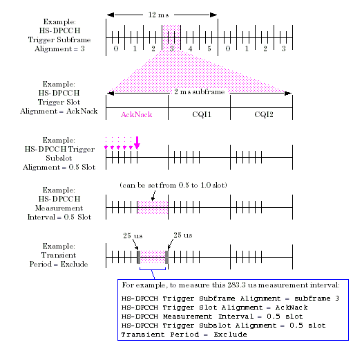
- Use the HS-DPCCH Trigger Subframe Alignment setting to choose in which 2 ms subframe (0 to 5) you want to place the measurement interval.
-
Use the
HS-DPCCH Trigger Slot Alignment
setting to specify in which slot within the subframe you want to place the measurement interval (
AckNack= the first slot of the subframe,CQI1= the second slot of the subframe andCQI2= the third slot of the subframe). -
Set the duration of the measurement interval using the
HS-DPCCH Measurement Interval
setting. Note that the sum of
HS-DPCCH Trigger Subslot AlignmentandHS-DPCCH Measurement Intervalcannot exceed 1.0 slot. -
Use the
HS-DPCCH Trigger Subslot Alignment
setting to specify where you want to place the measurement interval within the slot. You can place the measurement interval at the slot boundary, 0.1 slot (66.7 us) after the slot boundary, 0.2 slot (133.3 us) after the slot boundary... up to 0.5 slot (333.3 us) after the slot boundary. Note, however, that the sum of
HS-DPCCH Trigger Subslot AlignmentandHS-DPCCH Measurement Intervalcannot exceed 1.0 slot. If you wish to place the measurement interval after the slot boundary using theHS-DPCCH Trigger Subslot Alignmentsetting, you must first decrease theHS-DPCCH Measurement Intervalsetting appropriately. -
You can choose to shorten the measurement interval so as to exclude the 25 us (96 chip) transient periods at the start and end of the measurement interval using the
Transient Period
setting. For example, if you set
HS-DPCCH Measurement Intervalto0.5 slot(333.3 us or 1280 chips) and setTransient PeriodtoExclude, the measurement is performed over 283.3 us (or 1088 chips).
Code Domain Measurement Parameters
-
Timeslot
When Trigger Source is set to any value other than
HS-DPCCH, you can specify which timeslot of the W-CDMA frame (0 to 14) is evaluated by the code domain measurement. See Measurement Interval in Non-HSDPA Mode . - Trigger Arm: see Trigger Arm (Single or Continuous) Description .
-
Trigger Source
Triggering choices are immediate, protocol, external, auto, HS-DPCCH and Even Frame.
Auto triggering is the default choice. In most cases, auto triggering provides the optimum measurement triggering condition for the code domain measurement. For example, if the UE is synchronized to the test set, auto triggering causes protocol triggering to be used. Auto triggering causes immediate triggering is used if the UE is not synchronized. When immediate triggering is used, the measurement result returned for timing error is always
NAN(Not a Number) because it is not possible to evaluate a timing error in this measurement situation. See Trigger Source Description for more information.HS-DPCCH ( lab application or feature-licensed test application only ): This
Trigger Sourceis only available while on an HSDPA connection. See Trigger Source Description .Even Frame ( lab application or feature-licensed test application only ): This
Trigger Sourceis only available while on an HSPA connection. WhenTrigger Sourceis set toEven Frame, the measurement triggers every 20 ms, in alignment with the 10 ms system frame clock. Whether the trigger occurs on odd-SFN or even-SFN frames is determined by the SFN Alignment setting. - Measurement Timeout: see Measurement Timeouts .
-
SFN Alignment
When
Trigger Sourceis set toEven Frame, this setting determines whether the trigger occurs on odd-SFN or even-SFN frames.
HSDPA Measurement Parameters
This section is only applicable to the lab application or feature-licensed test application .
These settings are only applicable when
Trigger Source
=
HS-DPCCH
.
See Measurement Interval in HSDPA Mode for more information about using these parameters to specify the duration and placement of the measurement interval.
-
Transient Period
When
Transient Periodis set toInclude, the measurement is performed over the interval specified by the HS-DPCCH Measurement Interval setting.When
Transient Periodis set toExclude, the 25 us at the start of the measurement interval and the 25 us at the end of the measurement interval are excluded from the measurement. Thus, the measurement is performed over an interval equal to HS-DPCCH Measurement Interval minus 50 us. See Measurement Interval in HSDPA Mode . -
HS-DPCCH Trigger Subframe Alignment
Selects which 2 ms subframe (0 to 5) contains the measurement interval.
-
HS-DPCCH Trigger Slot Alignment
Selects which slot in the 2 ms subframe contains the measurement interval (
AckNack= the first slot in the subframe,CQI1= the second slot in the subframe andCQI2= the third slot in the subframe). -
HS-DPCCH Measurement Interval
See Measurement Interval in HSDPA Mode .
Note, the sum of HS-DPCCH Trigger Subslot Alignment and
HS-DPCCH Measurement Intervalcannot exceed 1.0 slot. -
HS-DPCCH Trigger Subslot Alignment
Selects where to place the measurement interval within the slot, in 0.1 slot (66.7 us) increments. This is useful because depending upon the Current DPCH Offset , the uplink DPCH and HS-DPCCH can be offset in time by increments of 0.1 slot (see HS-DPCCH/DPCCH Alignment vs. DPCH Frame Offset ).
Note, the sum of
HS-DPCCH Trigger Subslot Alignmentand HS-DPCCH Measurement Interval cannot exceed 1.0 slot.
Code Domain Measurement Results
-
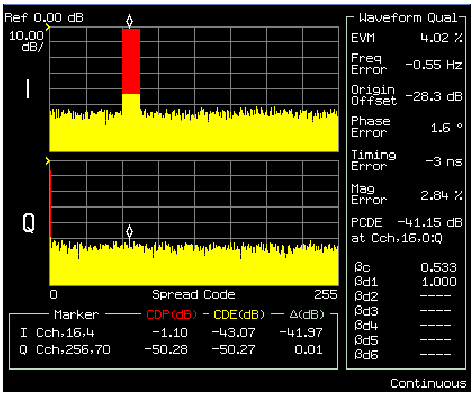
Graph of Code Domain Power and Code Domain Error results.
- The x axis always has a resolution of 256 codes (SF=256).
- The CDP and CDE are computed in the correct spreading factor for the DPCCH and DPDCH as defined for the channel type used. For example, in the graph below the 64k RMC is used. Therefore, the DPDCH occupies C ch,16,4 as defined in the 3GPP standards. (C ch,Spreading Factor,Code Number )

-
Code Domain Power (CDP)
CDP is the ratio of the measured code domain power to the total power of the input signal.
-
Code Domain Error (CDE)
CDE is the ratio of the mean power of the error vector projection onto the code to the mean power of the composite reference waveform. See 3GPP TS 25.101 s6.8.3.
-
Relative Code Domain Error (RCDE)
RCDE is computed by projecting the error vector onto the code domain. The RCDE for every non-zero beta code in the domain is defined as the ratio of the mean power of the error vector projection onto the non-zero beta code, to the mean power of the non-zero beta code in the composite reference waveform. RCDE is available for the active code channels only (code channels with non-zero beta values in the composite reference waveform). See 3GPP TS 34.121 s5.13.2A.
-
Relative Code Domain Power Accuracy (RCDPA)
RCDPA is a measure of the UE's ability to correctly set the level of individual code powers relative to the total power of all active codes. RCDPA is available for the active code channels only (code channels with non-zero beta values in the composite reference waveform). RCDPA is defined as the difference between the Measured CDP ratio and the NCDP ratio. Note that the Measured CDP ratio = 10*log 10 ((Measured code power)/(Measured total power of all active codes)), which is not the same as the Code Domain Power (CDP) result (which is relative to the total power of the input signal). See 3GPP TS 25.101 s6.2.3.
-
Nominal Code Domain Power (NCDP)
NCDP is the ratio of nominal code domain power to the sum of all nominal code domain powers. NCDP is available for the active code channels only (code channels with non-zero beta values in the composite reference waveform). See 3GPP TS 25.101 s6.2.3.
-
Effective Code Domain Power (ECDP)
ECDP k = (Measured CDP) k + 10*log 10 (SF k /256), where k represents the active code channel on which the ECDP is calculated. ECDP is available for the active code channels only (code channels with non-zero beta values in the composite reference waveform). See 3GPP TS 25.101 s6.8.3.
- All of the measurement results of the Waveform Quality measurement. Waveform Quality Measurement Results
-
Beta
ec
, Beta
ed1
, Beta
ed2
Beta ec , Beta ed1 , Beta ed2 provide results (other than NaN) when on an HSPA connection ( lab application or feature-licensed test application only ).
Code Domain Input Signal Requirements
- For this measurement the test set's receiver uses auto-ranging to adjust for the level of the signal being measured; therefore the expected signal level does not need to be specified during measurement setup. However, it is recommended that Expected Power be configured to match the actual signal level expected to ensure the auto-ranging procedure executes as quickly as possible.
- The frequency of the signal being measured must be in the range of 800 MHz to 1000 MHz, or from 1700 MHz to 1990 MHz.
- The level into the test set's RF IN/OUT connector must be in the range of +5 dBm to +28 dBm, in a 3.84 MHz bandwidth.
- Maximum measurable EVM = 35%
- Maximum measurable frequency error = ± 1 kHz
- Maximum measurable timing error = +/- 50 chips
Code Domain Measurement Calibration
This measurement should be calibrated using the Calibrate Measurements function ( CALibration:MEASurements? ) when the temperature has changed by ± 10° C or more since the last calibration. If this situation exists, the integrity indicator value becomes 19 and a message is displayed indicating "Uncalibrated Due to Temperature".

