How Do I Make an Extended Range Dynamic Power Measurement?
Last updated: January 15, 2009
Measuring Extended Range Dynamic Power
This procedure assumes the test set is in
Active Cell
Operating Mode. However, this measurement is also available in
FDD Test
Operating Mode.
-
Set the test set's receiver to the proper power and frequency for your UE's power sequence:
-
Select
Receiver Control( F12 onCall Parms 3 of 3). -
Set
Power ControltoManual. -
Set
Manual Powerto the maximum power level expected in the first power sequence. For example, 13 dBm. -
Set
Measurement Frequencyto the frequency at which the UE will transmit its power sequences (for example, 1 GHz).
-
Select
-
Press the
Measurement selection
key, select
Extended Range Dynamic Power. -
Select
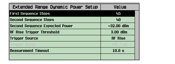
Ext Range Dyn Power Setup( F1 ) and set the measurement parameters as needed.-
Set
First Sequence Stepsto the number of the steps in the UE's first power sequence (for example, 45). The number of the steps can be 1 to 84. NOTE: The total number of First Sequence Steps andSecond Sequence Stepscan not exceed 85. -
Set
Second Sequence Stepsto the number of the steps in the UE's second power sequence (for example, 40). The number of the steps can be 1 to 84. NOTE: The total number of First Sequence Steps andSecond Sequence Stepscan not exceed 85. -
Set
Second Sequence Expected Powerto the maximum power level expected in the UE's second power sequence (for example, -32 dBm). The test set requires re-ranging its receiver after completing the first power sequence and before measuring the second power sequence. You must command your UE to transmit for 15 power steps (timeslots) with constant or varied power levels between the two power sequences you desire to measure, to allow test set to re-range its receiver. The test set does not make any measurement during this period. -
Set
Trigger SourcetoRF Rise. -
Set
RF Rise Trigger Thresholdas needed. It is recommended that you setRF Rise Trigger Thresholdto approximately 10 dB below theManual Power. For example, 3 dBm. -
Select
Close Menu( F6 ).

-
Set
-
Place your UE into a test mode. To ensure that the measurement is successfully triggered, order your UE to transmit continuously at a low power level (for example, -20 dBm) so that the first power step in the power sequences will meet the requirements of the RF rise trigger (the trigger pulse should rise in power by at least 20 dB and above the
RF Rise Trigger Thresholdlevel. See Triggering the Extended Range Dynamic Power Measurement for details). - Press the START SINGLE key to initiate (arm) the measurement.
-
Order your UE to begin transmission of the power sequences (two power sequences to be measured and 15 power steps (timeslots) in the middle of the two power sequences for test set re-ranging its receiver. The test set does not make any measurement during the receiver re-ranging period).
Do not send any GPIB commands to the test set or press any front panel keys until the measurement has completed.IMPORTANT
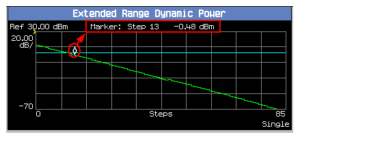
When the measurement completes, the power results are displayed on the test set's screen. An example result is shown below.

- If needed, select
Axis Control( F2 ). Set the axis parameters as needed and then selectReturn( F6 ).- If needed, select
Marker( F3 ) to turn on the marker on the graphical display. The power level of the step as specified by the marker is also displayed at the top of the window.Related Topics
Extended Range Dynamic Power Measurement Description
Extended Range Dynamic Power Measurement Troubleshooting
- If needed, select