Extended Range Dynamic Power Measurement Description
Last updated: January 16, 2009
- How is an Extended Range Dynamic Power Measurement Made?
- Extended Range Dynamic Power Measurement Parameters
- Extended Range Dynamic Power Measurement Results
- Extended Range Dynamic Power Input Signal Requirements
- Calibrating the Extended Range Dynamic Power Measurement
How is an Extended Range Dynamic Power Measurement Made?
The Extended Range Dynamic Power measurement allows you to measure the UE's transmitter output power across its entire dynamic power (up to 90 dB) in one measurement cycle. This measurement does not require a call established between the test set and UE since it does not utilize any overhead signalling to control the UE's power or frequency. Rather, you must place your UE into a test mode which forces it to transmit two power sequences you desire to test, and then analyze the resulting UE output power using the test set.
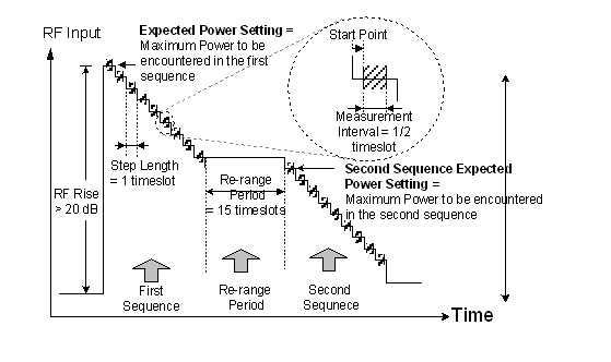
The Extended Range Dynamic Power measurement can measure power between -61 dBm and +28 dBm. Two power sequences output from the UE can be measured in one measurement cycle and the power range of each power sequence must not span more than 45 dB. Therefore, to measure a power range greater than 45 dB, you must break the power range up into two power sequences that do not exceed 45 dB. Each power sequence can contain up to 84 power steps (the levels can step up and/or down with varying magnitudes of change and the length of each step is fixed to one timeslot (666.7 us)). The sum of the steps in the two power sequences can not exceed 85 power steps. Moreover, you must command your UE to transmit for 15 power steps (timeslots) with constant or varied power levels between the two power sequences you desire to measure because the measurement must re-range its receiver in the middle of the two power sequences. The test set does not make any power measurements during the 15 timeslots re-range period. For example, to measure a UE's output power ranging from +24 dBm to -51 dBm, it is recommended that you command your UE to output the first power sequence stepping through the range of +24 dBm to -13 dBm in 1 dB step size, then hold its power constant for 15 timeslots, and then output the second power sequence stepping through the power range of -14 dBm to -51 dBm in 1 dB step size. The test set measures a total of 76 steps (timeslots) in one measurement and returns 76 power results for each step.
The figure below shows a typical example of UE output power sequence for the Extended Range Dynamic Power measurement.
The Extended Range Dynamic Power measurement can be made in Active Cell Operating Mode or FDD Test Operating Mode . Before starting the measurement, you must first set Measurement Frequency to the expected UE transmitter frequency and set Manual Power to the maximum expected power. To best utilize the 45 dB dynamic range of the test set's receiver, Manual Power should be set to the highest power expected in the first power sequence and Second Sequence Expected Power should be set to the highest power expected in the second power sequence. You must specify the number of steps in both sequences ( First Sequence Steps and Second Sequence Steps ), configure the trigger ( Trigger Source , RF Rise Trigger Threshold or Trigger Delay ), initiate the measurement, then order the UE to send its power sequences.
When the Extended Range Dynamic Power measurement is initiated, it waits for an RF rise trigger from the UE or an external trigger (see
Triggering the Extended Range Dynamic Power Measurement
). Once triggered, the test set starts to measure the UE output power sequences. It first samples the signals for the number of steps (timeslots) specified by the
First Sequence Steps
, then re-ranges its receiver according to the setting of
Second Sequence Expected Power
during the next 15 timeslots re-range period (the test set does not make any measurement during the re-range period), and after that, samples the signal for the number of timeslots specified by the
Second Sequence Steps
. When all of the power steps in both power sequences are sampled (with RRC filter off), the test set analyzes the power of each step and then returns the power results for all measured steps. The power result of each step is determined by averaging over a half timeslot measurement interval (0.5 timeslot = 333.3 us). When the
Trigger Source
is
RF Rise
, the measurement interval is centered in the middle of each step (666.7 us). That is, the measurement interval shall be at 166.7 us relative to the start of each step. When the
Trigger Source
is
External
, you can use the
Trigger Delay
to specify when the measurement interval should begin.
Triggering the Extended Range Dynamic Power Measurement
The measurement can be triggered externally or by an RF rise trigger in the power sequence.
-
You can trigger the Extended Range Dynamic Power measurement using an RF rise within the power sequence by setting the
Trigger Source
to
RF Riseand specifying the appropriate RF Rise Trigger Threshold . To ensure a successful RF rise triggering, it is recommended that you do the following:-
Set
Power Control
to
Manualand set Manual Power to the highest power expected in the first power sequence. It is also recommended that the RF Rise Trigger Threshold be set to approximately 10 dB below the highest power expected in the first power sequence. -
Order the UE to transmit continuously at a low power level to ensure that the first power step in the power sequences meets the requirements of the RF rise trigger. The trigger pulse should rise in power by at least 20 dB and above the
RF Rise Trigger Thresholdlevel. If the first power step you desire to measure meets the trigger pulse requirements, no separate trigger pulse is needed. Otherwise, you should include a separate power step as a trigger pulse in the first power sequence that you desire to measure. - Initiate the Extended Range Dynamic Power measurement by sending the INITiate:WEDPower command or by pressing the START SINGLE hardkey if running the measurement from the front panel (this is to arm the measurement).
- Send the INITiate:WEDPower:ARMed? query and wait for it to return a value of 1, indicating that the measurement is armed and ready to be triggered.
-
Order the UE to begin transmission of its power sequences to be measured. Since the power level of the first step in the first power sequence is above the
RF Rise Trigger Thresholdlevel, this causes the measurement to be triggered on an RF rise signal.
-
Set
Power Control
to
-
You can also use an external trigger source by setting the
Trigger Source
to
Externalas needed for your test cases. WhenExternalis selected as your trigger source, you are allowed to adjust the Trigger Delay .
Operating Considerations
- You must command your UE to transmit for 15 power steps (timeslots) with constant or varied power levels between the two power sequences you desire to measure because the measurement requires re-ranging its receiver after completing the first power sequence and before measuring the second power sequence. The test set does not make any power measurements during the 15 timeslots re-range period.
- To obtain the optimum measurement accuracy, it is recommended that the power range of each power sequence not exceed 45 dB. Also, to best utilize the 45 dB dynamic range of the receiver, Manual Power should be set to the highest power expected in the first power sequence and Second Sequence Expected Power should be set to the highest power expected in the second power sequence.
- You must set the First Sequence Steps and Second Sequence Steps to match the power sequences to be transmitted by the UE. Also, the sum of the two settings can not be more than 85 steps.
- No other measurements can be running when a Extended Range Dynamic Power measurement is performed. If any measurements are running when a Extended Range Dynamic Power measurement is initiated, they are closed and a message is displayed to indicate that they were closed. Likewise, if any other measurements are initiated while an Extended Range Dynamic Power measurement is running, the Extended Range Dynamic Power measurement is closed and a message is displayed.
- During front panel operation of this measurement, you must press the START SINGLE key to start the measurement.
- Do not send any GPIB commands to the test set or press any front panel keys until the measurement has completed.
Extended Range Dynamic Power Measurement Parameters
-
First Sequence Steps
Sets the number of steps (1 to 84) the UE will transmit during the first power sequence. The length of each step is fixed to one timeslot (666.7us). The UE's output power steps up or down through the first power sequence, which must not exceed 45 dB power range.
Note: The sum of First Sequence Steps and Second Sequence Steps can not be more than 85 steps.
GPIB command: SETup:WEDPower:STEPs:FSEQuence
-
Second Sequence Steps
Sets the number of steps (1 to 84) the UE will transmit during the second power sequence. The length of each step is fixed to one timeslot (666.7us). The UE's output power steps up or down through the second power sequence, which must not exceed 45 dB power range.
Note: The sum of the First Sequence Steps and Second Sequence Steps can not be more than 85 steps.
GPIB command: SETup:WEDPower:STEPs:SSEQuence
-
Second Sequence Expected Power
Sets the maximum expected power that the UE will transmit during the second power sequence. It should be set to the highest power in the second power sequence to best utilize the 45 dB dynamic range of the receiver.
The test set ranges its receiver based on the
Manual Powersetting for the first power sequence measurement (it is recommended you set the Manual Power to the highese power in the first power sequence) and then re-ranges it receiver based on theSecond Sequence Expected Powersetting for the second power sequence.GPIB command: SETup:WEDPower:SSEQuence:EXPected:POWer
-
RF Rise Trigger Threshold
This setting is only applicable when the Trigger Source is set to
RF Rise. When theTrigger Sourceis set toRF Rise, you must set theRF Rise Trigger Thresholdto the power level (in dBm) at which you want the measurement to trigger. When the power of the UE's signal rises above theRF Rise Trigger Thresholdlevel, the measurement is triggered.The
RF Rise Trigger Thresholdmust be set to within 0 dB to -25 dB of Manual Power (it is suggested that you setManual Powerto the highest power level of the first power sequence to best utilize the 45 dB dynamic range of the receiver). Also, it is recommended that theRF Rise Trigger Thresholdbe set to approximately 10 dB below the Manual Power .The test set assumes a crest factor of 3.1 dB for the signal (as is typical for an uplink DPCH signal relative to a CW signal) and thus actually triggers when the input signal reaches the
RF Rise Trigger Thresholdlevel plus 3.1 dB. If the UE's signal has a crest factor other than 3.1 dB, you must set theRF Rise Trigger Thresholdlevel accordingly.GPIB command: SETup:WEDPower:TRIGger:THReshold
-
Trigger Source
You may set
Trigger SourcetoRF Riseor External. IfTrigger Sourceis set toRF Rise, you must characterize the trigger using the RF Rise Trigger Threshold .For more information on these trigger types, see Trigger Source Description .
GPIB command: SETup:WEDPower:TRIGger:SOURce
-
Trigger Delay
The power level of each step is measured by averaging over a half timeslot measurement interval (0.5 timeslot = 333.3 us). When the Trigger Source is
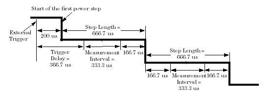
External, you can move the measurement interval of the first power step relative to the external trigger using theTrigger Delaysetting. The measurement intervals for all subsequent steps are then spaced by one timeslot. To make the power measurement of each step always be centered in the middle of the step, you should set theTrigger Delayto the time offset between the external trigger and the start of the first power step plus 166.7 us.When the Trigger Source is
RF Rise, the power measurement is averaged over 0.5 timeslot measurement interval (333.3 us) that is always centered in the middle of each step. Therefore, the measurement interval starts at 166.7us relative to the start of each step.For example, if the UE began to output its power sequences at 200 us delay after the external trigger, you should set Trigger Source to
ExternalandTrigger Delayto366.7 us. Thus, the power of each step is averaged for a half timeslot (333.3 us) that is centered in the middle of the step (since the length of each step is fixed to one timeslot (666.7 us) and the measurement interval is fixed to half timeslot (333.3 us)).GPIB command: SETup:WEDPower:TRIGger:DELay
-
Measurement Timeout - see
Measurement Timeouts
. Ensure that you set the
Measurement Timeoutto a value great enough to allow you to command the UE to transmit its power sequences and for the test set to measure the power sequences.GPIB command: SETup:WEDPower:TIMeout[:STIMe]
Extended Range Dynamic Power Measurement Results
- Integrity Indicator (see Integrity Indicator )
-
Number of Steps Measured
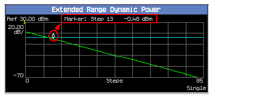
The number of steps measured should be the sum of the First Sequence Steps and Second Sequence Steps settings. It can be queried using the FETCh:WEDPower or FETCh:WEDPower:STEPs command (see FETCh:WEDPower ). It is also displayed on the front panel graphical display (see the figure below).
-
Average Power for Each Step (in dBm)
The test set measures the average power for each step by performing a channel power measurement (with RRC filter off) over a measurement interval of 333.3 us (one half timeslot). The measurement interval is centered in the middle of the 666.7 us (timeslot) step when Trigger Source is
RF Rise, or is offset from the start of the step according to the Trigger Delay setting when Trigger Source is set toExternal.You can retrieve the average power measured for each step using the FETCh:WEDPower command or from the front panel (see the figure below).

Extended Range Dynamic Power Input Signal Requirements
The Extended Range Dynamic Power measurement can measure power between -61 dBm and +28 dBm.
The dynamic range for each power sequence is 45 dB. That is, the UE's power can not vary by more than 45 dB in any of the two power sequences.
Calibrating the Extended Range Dynamic Power Measurement
You must calibrate this measurement using the measurement calibration procedure (see Calibrating the Test Set ).
Related Topics
Manual Operation: How Do I Make an Extended Range Dynamic Power Measurement?
Programming an Extended Range Dynamic Power Measurement
Extended Range Dynamic Power Measurement Troubleshooting

