How Do I Make an Inner Loop Power Measurement?
Last updated: January 15, 2009
Measuring 3GPP TS 34.121 5.4.2 Inner Loop Power Control in the Uplink
- Ensure that you have specified the proper Amplitude Offset for your test setup.
- Ensure that the test set has been properly calibrated (see Calibrating the Test Set ).
-
Set the downlink and uplink channels:
-
Set
Operating Mode( F1 ) toCell Off. -
Set
DL Channel( F10 ) andUplink Channel( F11 ) to the appropriate "mid range" frequencies for your UE's operating band, as specified by 3GPP TS 34.108 5.1.1 (for example, for operating band I,DL Channel=10700andUplink Channel=9750). -
Set
Operating ModetoActive Cell.
-
Set
-
Establish an
RB Test Modeconnection between the UE and test set (see How Do I Set Up a Call and Make a Connection? ). -
Ensure that the
Connected DL Channel Levelsare set to their default values, as required by 3GPP TS 34.121 Table E.3.1 (selectGenerator Info, F3 onCall Control 2 of 5). -
Set
Cell Power( F7 ) to-93 dBm. - Press the Measurement selection key.
-
Select
Inner Loop Power. -
Select
Inner Loop Power Setup( F1 ). - Press the START SINGLE key.
-
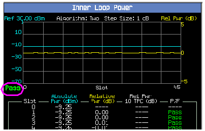
Verify that the overall test segment result is
Pass.
-
If desired, select
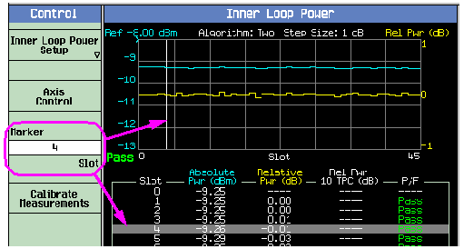
Axis Control( F2 ). -
If desired, select
Marker( F3 ) to turn on the marker on the graphical display and move the highlighted bar in the numerical results display area.
-
Select
Inner Loop Power Setup( F1 ). - Press the START SINGLE key.
-
Verify that the overall test segment result is
Pass. -
Repeat steps 14-16 for test segments C, E, F, G and H. Note: step D in 3GPP TS 34.121 5.4.2 is automatically performed as part of
Test Segment E. For test segments E through H, ensure thatMaximum Power Threshold for Test Controlis set toAuto,Maximum Output Power Test Toleranceis set to0.70 dB,Minimum Power Threshold for Test Controlis set toManual, andMinimum Power Threshold for Test Manualis set to-49 dBm(these are the default values), as required by 3GPP TS 34.121