How Do I Make a Spectrum Emission Mask Measurement?
Last updated: February 12, 2011
- Measuring Spectrum Emission Mask
- Measuring 3GPP TS 34.121-1 (v8.10.0) 5.9B Spectrum Emission Mask with E-DCH (lab application or feature-licensed test application only)
Measuring Spectrum Emission Mask
-
Establish an
RB Test Modeconnection between the UE and test set (see How Do I Set Up a Call and Make a Connection? ). - Press the Measurement selection key.
-
Select
Spectrum Emission Mask. -
Select
SEM Setup( F1 ) and set the measurement parameters as needed. SelectClose Menu( F6 ). -
If
Trigger Armis set toSingle, you must press the START SINGLE key to begin the measurement. -
Press the
Change View( F2 ) key to display the measurement results in either graphical or numeric format.
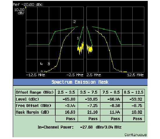
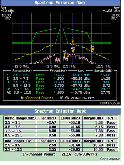
A typical result is shown below.

Measuring 3GPP TS 34.121-1 (v8.10.0) 5.9B Spectrum Emission Mask with E-DCH
This section is applicable to the lab application or feature-licensed test application only.
-
Set parameters that can only be set in cell off operating mode (and other parameters that are set from the same menu):
-
Set
Operating Mode( F1 ) toCell Off. -
Select
34.121 Preset Call Configurations( F11 onCall Parms 1 of 3) and select5.2B, 5.9B, 5.10B, and 5.13.2B:HSPA:QPSK, then select the desired sub-test. You may then skip any steps marked with [34.121 Call Config] in this procedure. -
Select
Channel (UARFCN) Parms( F12 onCall Parms 1 of 3). SetDL Channel( F7 ) to the appropriate "low range" frequency for your UE's operating band, as specified by 3GPP TS 34.108 5.1.1 (for example, for operating band II setDL Channel=9663). -
[34.121 Call Config]
Select
Uplink Parameters( F4 onCall Control 2 of 6).-
[34.121 Call Config]
Set
Uplink DPCH Bc/Bd ControltoManual. -
[34.121 Call Config]
Set
Manual Uplink DPCH Bcto11(for 34.121-1 v8.10.0 Table C.11.1.3 sub-test 1). -
[34.121 Call Config]
Set
Manual Uplink DPCH Bdto15(for 34.121-1 v8.10.0 Table C.11.1.3 sub-test 1). -
[34.121 Call Config]
Set
Maximum Uplink Transmit Power Levelto+21 dBm.
-
[34.121 Call Config]
Set
-
Set
Operating ModetoActive Cell(pressing the CALL SETUP key quickly brings you back to the top levelCall Controlmenu).
-
Set
-
Set
Cell Power( F7 onCall Parms 1 of 3) to-86 dBm/3.84 MHz. -
[34.121 Call Config]
Set
Channel Type( F8 ) to12.2k RMC + HSPA(for 34.121-1 v8.10.0 Table C.11.1.3 sub-test 1). -
[34.121 Call Config]
Select
Generator Info( F3 onCall Control 2 of 6), selectDownlink Channel Levels( F3 ), selectConnected DL Channel Levels( F3 ), then selectHSPA Conn DL Channel Levels( F4 ).-
[34.121 Call Config]
Set
HSPA Cell 1 Connected CPICH Levelto-10 dB(this is the default value). -
[34.121 Call Config]
Set
HSPA Cell 1 Connected P-CCPCH/SCH Levelto-12 dB(this is the default value). -
[34.121 Call Config]
Set
HSPA Cell 1 Connected PICH Levelto-15 dB(this is the default value). -
[34.121 Call Config]
Set
HSPA Cell 1 Connected (F-)DPCH Levelto-10 dB(this is the default value). -
[34.121 Call Config]
Set
HSPA Cell 1 Connected E-AGCH Levelto-20 dB(this is the default value). -
[34.121 Call Config]
Set
HSPA Cell 1 Connected E-HICH Levelto-20 dB(this is the default value). -
[34.121 Call Config]
Set
HSPA Cell 1 Connected E-RGCH LeveltoOff(this is the default value). -
[34.121 Call Config]
Set
HSPA Cell 1 Connected HS-PDSCHs Level (Sum)to-3 dB(this is the default value). -
[34.121 Call Config]
Set
HSPA Cell 1 Connected HS-SCCH 1 Levelto-8 dB.
-
[34.121 Call Config]
Set
-
[34.121 Call Config]
Select
HSUPA Parameters(HSPA Parameters( F10 ), F9 ).-
[34.121 Call Config]
Select
HSUPA RB Test Mode Setup( F8 ). -
[34.121 Call Config]
Select
Common HSUPA Parameters( F9 ).-
[34.121 Call Config]
Set
E-DPCCH/DPCCH Power Offset (DeltaE-DPCCH)to6(for 34.121-1 v8.10.0 Table C.11.1.3 sub-test 1). Note, 34.121-1 Table C.11.1.3 provides Beta ec (209/225 for sub-test 1). To determine what value of DeltaE-DPCCH corresponds to this, use 3GPP TS 25.213 Table 1B and the value of Beta c from 34.121-1 Table C.11.1.3 (11/15 for sub-test 1). For sub-test 1, A ec = Beta ec /Beta c = (209/225)/(11/15) = 19/15; therefore DeltaE-DPCCH = 6. -
[34.121 Call Config]
Set
Reference E-TFCI Power OffsetstoDefinition 34.121-01(for 34.121-1 v8.10.0 Table C.11.1.3 sub-test 1).
-
[34.121 Call Config]
Set
-
[34.121 Call Config]
Select
Serving Grant( F10 ).-
[34.121 Call Config]
Set
RB Setup AGto26: (119/15)^2(for 34.121-1 v8.10.0 Table C.11.1.3 sub-test 1). Note, 34.121-1 Table C.11.1.3 AG Index corresponds to 3GPP TS 25.212 s4.10.1A.1 Table 16B, which maps the Absolute Grants sent on the E-AGCH. To send the equivalent Absolute Grant in the RB Setup message, you must use the AG Index in 3GPP TS 25.321 s9.2.5.2.1.1 Table 9.2.5.2.1.1.
-
[34.121 Call Config]
Set
-
[34.121 Call Config]
Select
-
[34.121 Call Config]
Select
HSDPA Parameters(HSPA Parameters( F10 ), F10 ). -
Test Application: Select
Cell Parameters( F2 ).
Lab Application: SelectCell Info( F2 ), thenCell Parameters( F2 ).
( from theCall Control 2 of 6menu)-
Set
PS Domain InformationtoPresent(this is the default value in the lab application). -
Qqualmin and Qrxlevmin are fixed to -24 dB and -115 dBm, respectively, in the test application. In the lab application these are the default values for these parameters. They are accessible from
Cell Info,Reselection Parameters( F3 ).
-
Set
-
[34.121 Call Config]
Select
RB Test Mode Setup( F6 onCall Control 3 of 6) and setUE Loopback TypetoType 1(this is the default value). -
[34.121 Call Config]
Select
UL CL Power Ctrl Parameters( F8 onCall Parms 3 of 3) and setUL CL Power Ctrl AlgorithmtoTwo(this is the default value) (for 34.121-1 v8.10.0 Table C.11.1.3 sub-test 1). -
Set any other parameters needed to establish a connection with your UE, then power on the UE and wait for it to register (attach). See
Establishing an HSPA Connection
.
Note, before you can establish a connection in the PS domain (as is required for HSPA connections), the UE must attach to the test set. To enable this, thePS Domain Informationparameter must be set toPresentwhen the UE registers (attaches) with the test set. -
Select
Originate Call( F3 onCall Control 1 of 6). -
Drive the UE to maximum power:
-
Select
UL CL Power Ctrl Parameters( F8 onCall Parms 3 of 3) and setUL CL Power Ctrl ModetoActive bits(this is the default value). -
Set
UE Target Power( F7 onCall Parms 3 of 3) to2 dBm(for 34.121-1 v8.10.0 Table C.11.1.3 sub-test 1, power class 3 UE). This value is determined as follows: Maximum power for a power class 3 UE is +24 dBm, butUE Target Poweronly sets the DPCCH+DPDCH power level of the UE. In order to achieve a total output power of +16.5 dBm (24 dBm - 7.5 dB), you must setUE Target Powerto at most 16.5 dBm - Power change due to HS-DPCCH, E-DPCCH and E-DPDCH .
Power Change Due to HS-DPCCH, E-DPCCH and E-DPDCH = 10log 10 (Beta c ^2 + Beta d ^2 + Beta hs ^2 + Beta ec ^2 + Beta ed ^2) - 10log 10 (Beta d ^2 + Beta c ^2) = 14 dB for sub-test 1, so you must setUE Target Powerto 2 dBm for sub-test 1.
TheUE Target Powervalues for sub-tests 2-5 are as follows: sub-test 2: 11 dBm, sub-test 3: 3 dBm, sub-test 4: 14 dBm, sub-test 5: 6 dBm. - Wait 150 ms.
-
Press the
Measurement selection
key and select
Channel Power. - Set up the measurement:
- Observe the channel power measurement result to ensure that the UE's output power is at least 7.5 dB below max power (<16.5 dBm for power class 3 UEs).
-
Select
UL CL Power Ctrl Parameters( F8 onCall Parms 3 of 3). SetUL CL Power Ctrl ModetoAlternating bits(for 34.121-1 v8.10.0 Table C.11.1.3 sub-test 1). -
Select
Additional Screens( F1 fromCall Control 2 of 6), selectHSPA Information( F2 ) and observe theLast Received E-TFCI(it should be 75 for 34.121-1 v8.10.0 Table C.11.1.3 sub-test 1, 67 for sub-test 2, 92 for sub-test 3, 71 for sub-test 4 and 67 for sub-test 5). -
Select
E-TFCI Recording Information( F3 ) (for 34.121-1 v8.10.0 Table C.11.1.3 sub-test 1). -
Select
HSPA Parameters( F10 ),HSUPA Parameters( F9 ),E-TFCI Recording( F11 ),E-TFCI Recording Parameters( F7 ) (for 34.121-1 v8.10.0 Table C.11.1.3 sub-test 1):-
[34.121 Call Config]
Set
E-TFCI Recording Countto15(this is the default value). -
Select
Send Step Up TPC Bit Pattern( F10 ) and thenStart Recording E-TFCI Values( F8 ). - Observe whether the UE sent any decreased E-TFCI. If not, send another up TPC bit and record E-TFCI. Repeat until the UE sends at least one decreased E-TFCI.
-
Select
Send Step Down TPC Bit Pattern( F11 ) and thenStart Recording E-TFCI Values( F8 ). - Observe whether the UE sent any decreased E-TFCI. If it did, then send another down TPC bit, then continue to the next step. If not, continue to the next step.
- Confirm that the E-TFCI is equal to the target E-TFCI of 75 for sub-test 1. If not, fail the UE. Note that an E-TFCI of 75 corresponds to an uplink data rate of 2421 bits/10 ms = 242 kbps. The uplink data rate for sub-test 2 = 175 kbps, sub-test 3 = 483 kbps, sub-test 4 = 206 kbps and sub-test 5 =175 kbps.
-
[34.121 Call Config]
Set
-
Select
-
Press the
Measurement selection
key and select
Spectrum Emission Mask. - Set up the measurement.
-
Determine whether the results are within the range specified by 3GPP TS 34.121-1 tables 5.9B.3, 5.9B.3A, 5.9B.3B and 5.9B.3C.

-
To repeat this test for sub-tests 2-5:
-
Perform a Transport Channel Reconfiguration (
Handovers( F5 )) to change the following settings:Sub-test 2-5 Transport Channel Reconfiguration settings Setting Sub-test 2 Sub-test 3 Sub-test 4 Sub-test 5 TCR DPCH Bc/Bd Control Manual Manual Manual Manual TCR Manual Uplink DPCH Bc 6 15 2 15 TCR Manual Uplink DPCH Bd 15 9 15 0 TCR DeltaACK, DeltaNACK, DeltaCQI 8 8 8 0 TCR Ack-Nack Repetition Factor 3 3 3 3 TCR CQI Feedback Cycle (k) 4 ms 4 ms 4 ms 4 ms TCR CQI Repetition Factor 2 2 2 2 TCR E-DPCCH/DPCCH Power Offset 8 8 5 0 TCR Reference E-TFCI Power Offsets 34121-01 34121-02 34121-01 34121-03 TCR Absolute Grant 18: (47/15)^2 21: (67/15)^2 23: (84/15)^2 18: (47/15)^2 - For sub-tests 2-4, repeat steps 12 and 15.
-
For sub-test 5, end the call (
F3
) and proceed as follows.
-
Set
Channel Type( F8 ) toHSPA. -
Select
HSUPA RB Test Mode Setup( F8 ) and setRB E-DPDCH Max Channel Codes (HSPA)toSF4. -
Select
UL CL Power Ctrl Parameters( F8 onCall Parms 3 of 3) and setUL CL Power Ctrl AlgorithmtoOne. -
Select
Originate Call( F3 onCall Control 1 of 6). -
Drive the UE to maximum power:
-
Select
UL CL Power Ctrl Parameters( F8 onCall Parms 3 of 3) and setUL CL Power Ctrl ModetoActive bits. -
Set
UE Target Power( F7 onCall Parms 3 of 3) to6 dBm(for power class 3 UE). - Wait 150 ms.
- Observe the channel power measurement result (pressing the MEASUREMENT key quickly brings you to the channel power measurement screen) to ensure that the UE's output power is at least 7.5 dB below max power (<16.5 dBm for power class 3 UEs).
-
Select
UL CL Power Ctrl Parameters( F8 onCall Parms 3 of 3). SetUL CL Power Ctrl ModetoAll Up bits. - Wait 150 ms.
-
Select
- Repeat step 15.
-
Set
-
Perform a Transport Channel Reconfiguration (
- End the call (F3).
- Repeat the testing at mid and high range frequencies.
Related Topics
Spectrum Emission Mask Measurement Description