How Do I Make a TX Dynamic Power Measurement?
Last updated: January 15, 2009
Measuring TX Dynamic Power
This procedure assumes the test set is in Active Cell Operating Mode . However, this measurement is also available in FDD Test Operating Mode and CW Operating Mode .
- Set the test set's receiver to the proper power and frequency for your UE's power sequence:
- Press the Measurement selection key.
-
Select
TX Dynamic Power. -
Select
TX Dynamic Pwr Setup( F1 ). - Connect your UE to the test set's front panel RF IN/OUT connector and power it on.
- Once the UE is on and transmitting the initial transmit power level continuously, press the START SINGLE key to initiate (arm) the measurement.
-
Order your UE to create the necessary RF rise to trigger the measurement (see
How is a TX Dynamic Power Measurement Made?
). The UE should then hold its power at the initial transmit power level for the duration of
Power Step Time, then proceed with its step down power sequence. When the power sequence is complete, the power results are displayed on the test set's screen.
Do not send any GPIB commands to the test set or press any front panel keys until the measurement has completed.IMPORTANT
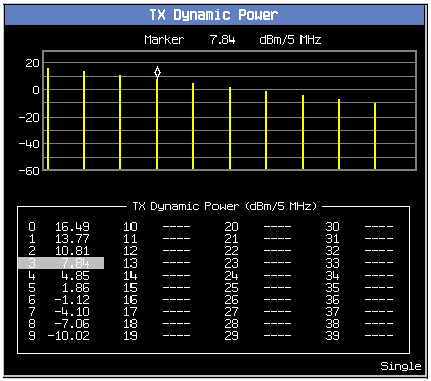
An example result is shown below. Note that the number of power results is always equal to the
Number of Power Stepssetting plus one, as the power in slot 0 is the initial power of the UE, before its first step down in power.
- Select
Graph Control( F2 ).- Set
Start Step( F3 ) andSpan( F4 ) as needed to view some or all of the power sequence.- Select
Marker( F2 ) to turn on the marker on the graphical display and move the highlighted bar in the numerical results display area.Related Topics
TX Dynamic Power Measurement Description
TX Dynamic Power Measurement Troubleshooting
- Select