Optical Connector Care
Damage to fiber-optic input connectors (as well as connectors on calibration and verification devices, test ports, cables, and other devices) can degrade measurement accuracy and damage instruments. Replacing a damaged fiber-optic connectors can cost thousands of dollars, not to mention lost time! This expense can be avoided by observing the important precautions described in the topics referenced below.
Treat all fiber-optic connectors like the high-quality lens of an expensive camera. Damage to the connectors on calibration and verification devices, test ports, cables, and other devices can:
- Degrade measurement accuracy and repeatability and
- Cause expensive damage to instruments.
Because fiber-optic connectors are susceptible to damage that is not immediately obvious to the naked eye, it is very easy to make bad measurements without being aware of a connector problem. Learning about proper handling and cleaning techniques will help you to avoid any degredation in connector performance. With glass-to-glass interfaces, any damage of the ferrule or end of the fiber, any stray particles, or finger oil can have a significant effect on connector performance.
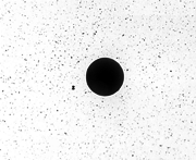
This picture shows the end of a clean, problem-free fiber-optic connector. The dark center circle is the fiber's 125 μm core and cladding which carries the light. The surrounding area is the soft nickel-silver ferrule. Click here to view connectors that have been damaged by improper handling!
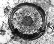
This picture shows a fiber end that is dirty from neglect or improper cleaning. Loose particles or oils are smeared and ground into the end of the fiber causing light scattering and poor reflection. Not only is the precision polish lost, but this action can also grind off the glass face and destroy the connector.
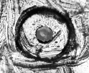
This picture shows physical damage to the glass fiber end caused by either repeated connections made without removing loose particles from the fiber end or by using improper cleaning tools. This damage can be severe enough to transfer the damage from the connector end to a good connector that comes in contact with it.
The cure for these problems is disciplined connector care. Visual inspection of fiber ends can be helpful. Contamination or imperfections on the cable end face can be detected as well as cracks or chips in the fiber itself. Use a microscope (100X to 200X magnification) to inspect the entire end face for contamination, raised metal, dents in the metal, and any other imperfections. Visible imperfections not touching the fiber core may not affect performance, unless the imperfections keep the fibers from contacting.
Always remove both ends of fiber-optic cables from any instrument, system, or device before visually inspecting the fiber ends. Disable all optical sources before disconnecting fiber-optic cables. Failure to do so may result in permanent injury to your eyes.
Improper connector care, cleaning, or use of mismatched cable connectors can invalidate the published specifications and damage connectors. Clean all cables before applying to any connector. Repair of damaged connectors due to improper use is not covered under warranty.
Guidelines
- Choose the right connector.
- If practical, monitor a connector's insertion loss and return loss so that you can catch any degradation before it affects your measurements.
- Use a fiber-optic inspection scope to visually inspect the fiber-optic end. Click here to view connectors that have been damaged by improper handling!
Always remove both ends of fiber-optic cables from any instrument, system, or device before visually inspecting the fiber ends. Disable all optical sources before disconnecting fiber-optic cables. Failure to do so may result in permanent injury to your eyes.
- Keep all fiber-optic connectors clean using professional fiber-optic cleaning products. Many products are available and are easily located via an internet search on "fiber optic cleaning products". You can purchase tools designed specifically for the type of fiber-optic connector that you are using.
- Never use metal or sharp objects to clean a connector and never scrape the connector.
- When inserting a fiber-optic cable into a connector, gently insert it in as straight a line as possible. Tipping and inserting at an angle can scrape material off the inside of the connector or even break the inside sleeve of connectors made with ceramic material. Ensure that the fiber end does not touch the outside of the mating connector or adapter.
Unlike common electrical connections, tighter is not better. The purpose of the connector is to bring two fiber ends together. Once they touch, tightening only causes a greater force to be applied to the delicate fibers. With connectors that have a convex fiber end, the end can be pushed off-axis resulting in misalignment and excessive return loss. Many measurements are actually improved by backing off the connector pressure. Also, if a piece of grit does happen to get by the cleaning procedure, the tighter connection is more likely to damage the glass. Tighten the connectors just until the two fibers touch.
- Keep connectors covered when not in use.
- Use fusion splices on the more permanent critical nodes. Choose the best connector possible. Replace connecting cables regularly. Frequently measure the return loss of the connector to check for degradation, and clean every connector, every time.
Keysight Technologies strongly recommends that index matching compounds not be applied to their instruments and accessories. Some compounds, such as gels, may be difficult to remove and can contain damaging particulates. If you think the use of such compounds is necessary, refer to the compound manufacturer for information on application and cleaning procedures.
| Connector | Description |
|---|---|
| FC | Flat endface, polished so that the glass ends up concave and slightly recessed from an otherwise flat face resulting in no glass to glass connection. |
| PC | Polished so that the whole endface, including the glass-fiber tip, ends up with a slight convex shape. The slight rounding brings the fiber up as the highest point on the endface ensuring a glass-to-glass connection. |
| APC | Connector with an angled endface that can achieve a better return loss. |
| DIN | Physically contacting connector. The DIN adapter accommodates both straight and angled connectors. |
| ST | Physically contacting connector with a bayonet sleeve (similar to an electrical BNC). |
| SC | Physically contacting connector with a snap-in styled sleeve. |
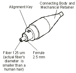
| HMS-10 | Keyed, physical contact connector with an inner ferrule used to hold the fiber into the desired position, producing more precise alignments. The HMS-10 encases the fiber within a soft nickel silver (Cu/Ni/Zn) center that is surrounded by a tough tungsten carbide casing |
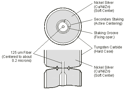
The nickel silver allows an active centering process that permits the glass fiber to be moved to the desired position. This process first stakes the soft nickel silver to fix the fiber in a near-center location, then uses a post-active staking to shift the fiber into the desired position within 0.2 μm. This process, plus the keyed axis, allows very precise core-to-core alignments. This connector is found on most Keysight Technologies lightwave instruments.
The soft core, while allowing precise centering, is also the chief liability of the connector. The soft material is easily damaged. Care must be taken to minimize excessive scratching and wear. While minor wear is not a problem if the glass face is not affected, scratches or grit can cause the glass fiber to move out of alignment. Also, if unkeyed connectors are used, the nickel silver can be pushed onto the glass surface. Scratches, fiber movement, or glass contamination will cause loss of signal and increased reflections, resulting in poor return loss.
Measuring Insertion and Return Loss
Test your cables for insertion loss and return loss upon receipt and retain the measured data. You will then be able to compare those figures to future measurement results and determine if any degradation has occurred.
Consistent measurements with your lightwave equipment are a good indication that you have good connections. Since return loss and insertion loss are key factors in determining optical connector performance they can be used to determine connector degradation. A smooth, polished fiber end should produce a good return-loss measurement. The quality of the polish establishes the difference between the "PC" (physical contact) and the "Super PC" connectors. Most connectors today are physical contact which make glass-to-glass connections, therefore it is critical that the area around the glass core be clean and free of scratches. Although the major area of a connector, excluding the glass, may show scratches and wear, if the glass has maintained its polished smoothness, the connector can still provide a good low level return loss connection.
Typical values are less than 0.5 dB of loss, and sometimes as little as 0.1 dB of loss with high performance connectors. Return loss is a measure of reflection: the less reflection the better (the larger the return loss, the smaller the reflection). The best physically contacting connectors have return losses better than 50 dB, although 30 to 40 dB is more common.
Refer to the manuals provided with your lightwave test equipment for information on how to perform an insertion loss and/or return loss test. Typical insertion loss for cables is less than 1 dB, and can be as little as 0.1 dB. Refer to the manufacturer specifications of your particular cable or accessory.