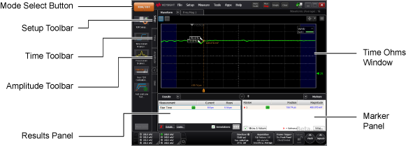
TDR/TDT Mode
Instrument:
N1000A
Flex Apps:
FlexDCA
Meas. mode:
TDR
Waveform type:
T-Parameter
S-Parameter

TDR/TDT mode provides the following measurement capability:
- Time Domain Reflectometry (TDR) and Time Domain Transmission (TDT) waveforms, which provide an intuitive view of a DUT's impedance profile (reflection and transmission characteristics) versus distance.
- T-parameter waveforms (time domain TDR/TDT graphs) with amplitude units in volts, ohms, or percent.
- S-parameter waveforms (frequency domain graphs) in magnitude, group delay, or phase. The frequency domain graphs allow you to view behaviors such as resonances. You can export S-parameters to a file. S-parameters are provided with option 202, S-Parameter and Time Domain Characterization.
TDR mode does not require a license, however the Signal Integrity or Manufacturing package licenses add significant capability:
- Enhanced impedance and S-parameters.
- Advanced waveform analysis (MATLAB/Python I/F).
- Automatic fixture removal (Signal Integrity package only)
Protect Your Investment!
- ESD Precautions
- Electrical Connector Care
- Coaxial Connector Types
Topics of interest
N1055A and 54754A TDR/TDT modules can be simultaneously installed. However, all TDR stimulus steps must originate from one type of module: either N1055A or 54754A.
These are the general measurement steps. For a more detailed procedure, refer to TDR Setup (DUT Based).
- In TDR/TDT mode, click the Setup toolbar.
- Click the TDR Setup… button and define the setup using the displayed dialog.
- Close the dialog and click on the TDR Calibration… button. Run a guided calibration. Supported ECal Modules.
- Once the TDR or TDT responses are displayed, use the Measurement toolbar to quickly measure any discontinuities.