83491/2/3/4A Clock Recovery Modules
Starting with firmware release A.06.90, 86100D Compatibility mode is no longer being actively tested and supported.
There are no designated channels for these modules; they are active as soon as they are installed in the instrument. The data signal is passed, with minimal insertion loss, to the reference receiver module. The modules produce two clock signals, recovered clock (made available to the instrument by way of a connector located on the module's rear panel) and front-panel clock. The recovered clock has a lower operating bandwidth, which results in less jitter present on the trigger signal and provides a more complete view of the jitter on the waveform data.
The minimum required 86100-series firmware version for these modules is A.03.01.
See Also
- Available Accessories
- Modules
Signals displayed using a data trigger are less reliable than using a recovered clock. Signals triggered on data can also vary depending upon the trigger level.
When you press the module's front-panel button to select Trigger On Data, the internal clock recovery circuits are bypased and the data directly passes (AC coupled) to the rear-panel recovered clock connector. It is similar to not having a clock recovery module and using a splitter to divide the input signal and routing one portion to the front-panel trigger input. While triggering on the data provides a quick method of checking the data waveform, be aware that the displayed response may be missing 75% of the data patterns. This happens because triggering occurs at either the 1-to-0 or 0-to-1 data transition, and, as a result, only portions of data patterns having transition edges will be included in the eye diagram. For example, consider a pattern such as 1111000. Only the transition between the 1-to-0 will be displayed. Transitions between adjacent lows and highs will be lost. In addition, signals triggered on data can also vary depending upon the trigger level.
| Module | Maximum Signal Input | Damage Level |
|---|---|---|
| 83491A | ±5V | ±5V |
| 83492A | ±3 dBm | +10 dBm |
| 83493A | ±3 dBm | +10 dBm |
| 83494A | ±3 dBm | +10 dBm |
To use the front panel clock, 83494A modules require an instrument with the enhanced trigger option to recover the clock at 9.953 GBd (standard module) and 10.664 GBd (Option 106).
Avoid selecting a symbol rate that is a multiple of the input signal. For example, do not select a 622 MBd symbol rate if the signal is really at 155 MBd.
Notice that on the 83491/2/3/4A clock recovery modules there may be two symbol rates that share an LED. One rate is written in green text, the other rate is red. The LED will be either green or red, corresponding to one of the two rates.
If the Unlocked light is on, clock recovery cannot be established on the signal. Make sure that you have selected the correct symbol rate and that the instrument mainframe trigger level is adjusted appropriately.
Front-Panel Features
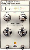
83491A
83492A
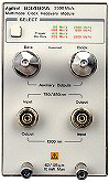
83493A

83494A
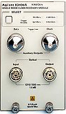
SELECT Button
Press this button to change the modulation rate of the input signal. The recovered and retimed clock trigger is sent to the mainframe. You can select one of the available symbol rates or you can select Trigger On Data. The Trigger On Data mode allows the data stream to directly trigger the mainframe.
Trigger On Data Indicator
The Trigger On Data selection is a bypass mode in which the data stream directly triggers the instrument mainframe.
Trigger Loss Indicator
This 83494A and 83494A Option 106 indicator, lights when clock recovery cannot be established on the signal. If a clock rate is selected, the trigger output to the mainframe is disabled to prevent free-run triggering. In bypass mode (Trigger On Data selected), triggering is not disabled. When the Trigger Loss light is on, you can establish a trigger on the data input to the reference receiver.
Green and Red Data-Rate Lights 83491/2/3 and 83494A Option 106
The data-rate indicator lights change color between red and green to show which symbol rate is selected. A red light does not indicate a problem. A red light shows that the adjacent red symbol rate label is selected. A green light shows that the adjacent green symbol rate label is selected. Repeatedly pressing the SELECT button cycles through the selections in one color before switching to the opposite color. On 83491A modules for example, the first selection cycle shows 155 MBd selected. The second selection cycle shows 1062 MBd selected.
Data-Rate Lights (83494A modules)
Green data-rate indicator lights show which symbol rate is selected. Repeatedly pressing the SELECT button cycles through the available symbol rates, as well as the Trigger On Data bypass mode. 83494A Option 106 modules use green and red data-rate indicator lights to show which symbol rate is selected. A red light does not indicate a problem. A red light shows that the adjacent red symbol rate label is selected. A green light shows that the adjacent green symbol rate label is selected.
UNLOCKED Indicator
Available on the 83491/2/3A modules, the Unlocked indicator lights when clock recovery cannot be established on the signal. If a clock rate is selected, the trigger output to the mainframe is disabled to prevent free-run triggering. In bypass mode (Trigger On Data mode selected), triggering is not disabled. When the Unlocked light is on, you can establish a trigger on the data input to the reference receiver.
Data Connector
The Data connector provides a fully regenerated version of the input signal. It is intended for monitoring purposes only and not for rigorous eye mask compliance testing. The frequency response does not conform to the requirements for eye mask testing as described in ITU-T G.957 and Bellcore GR-253-CORE. On 83492A and 83493A modules, this port is amplitude stabilized for input signals greater than approximately –23 dBm. On 83494A modules, this port is amplitude stabilized for input signals greater than approximately –10 dBm. The Clock Auxiliary Output remains synchronized to input signals several dB below the onset of errors at the Data Auxiliary Output .
Clock Connector
The Clock connector provides the recovered clock signal. You can use this signal to measure jitter transfer, because this output can track and follow input data with very fast jitter; it has a wide bandwidth jitter transfer function when compared to the recovered clock signal which is routed through a rear-panel connector to the mainframe for triggering. The Clock Auxiliary Output remains synchronized to input signals several dB below the onset of errors at the Data Auxiliary Output.
Input and Output Connectors
The input connectors pass the digitally modulated signal to the receiver module. The input signal is slightly attenuated and available at the Output connector. The input signal is also connected to the input of any of the Keysight 8348x or 861xx series modules. The connectors on optical modules include adapters that can easily be changed to match the type of connectors that are used on your fiber-optic cables.
Light energy can radiate from the front panel OUTPUT connectors on Keysight 83492A, 83493A, and 83494A modules. The light emitted from these connectors is the slightly attenuated light that is input to the front-panel INPUT connector.
The Keysight 83492A module uses multimode fiber. Connecting the output to the Optical Input connector on single-mode modules results in large reflections and insertion loss.
Keysight 83493A and 83494A modules use 9/125 μm single-mode fiber. Connecting multimode fiber to the Optical Input connector results in large reflections and insertion loss.