Linear Equalizer Operator (Advanced)
The Advanced tab allows you to specify the pattern symbol sequence, the equalizer's bandwidth, and select aliased noise processing.
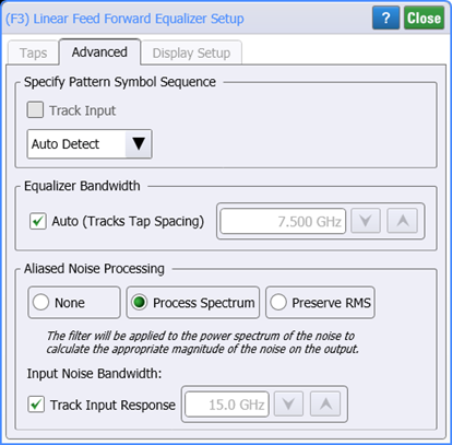
Specify Pattern Symbol Sequence
By default, the pattern symbol sequence is set to be automatically detected. However, you can change this to be either a standard Known Pattern (NRZ or PAM4), or a BERT Pattern File (*.ptrn). The following table lists the available known patterns. If you select to import a Pattern File, you can specify if the pattern uses Gray Coding. Gray coding, or reflected binary code, is a coding pattern where successive symbols differ by one binary bit. For example in the case of PAM4, binary bit sequences 00, 01,10, and 11 represent levels 0, 1, 2, and 3.
Pattern Length Selections
Availability of individual patterns depends on installed modules and other conditions.
- 20 - 2˄7-1 PRBS
- 40 - PCIe Compliance
- 62 - PAM4 Clock
- 120 - FC RPAT
- 160 - PAM4 Linearity
- 384 - 802.3ae TWDP segment
- 640 - PCIe Idle
- 1280 - FDDI Jitter
- 2280 - CRPAT
- 2640 - CJPAT
- 3360 - CRPAT (2)
- 3760 - CJPAT (2)
- 3780 - XAUI CRPAT
- 3820 - XAUE CJPAT
- 5280 - GbE Test Frame
- 7641 - XAUI CJPAT
- 9000 - JTPAT
- 18944 - CEI Stress
- 20480 - SPAT
- 20840 - CSPAT
- 21760 - CJTPAT
- 30240 - XAUI CRPAT
- 32762 - CEI SSPR
- 33792 - 10GbE
- 65535 - SSPRQ
- 90000 - FDDI Wander
- 92160 - SATA
- 311040 - SONET CID
- 127 - 2˄7-1 PRBS
- 128 - 2˄7 PRBS
- 511 - 2˄9-1 PRBS
- 512 - 2˄9 PRBS
- 1023 - 2˄10-1 PRBS
- 1024 - 2˄10 PRBS
- 2047 - 2˄11-1 PRBS
- 2048 - 2˄11 PRBS
- 8191 - 2˄13-1 PRBS
- 8192 - 2˄13 PRBS
- 32767 - 2˄15-1 PRBS
- 32768 - 2˄15 PRBS
- 65535 - 2˄16-1 PRBS
- 65536 - 2˄16 PRBS
- 1048575 - 2˄20-1 PRBS
- 1048576 - 2˄20 PRBS
- 8388607 - 2˄23-1 PRBS
- 8388608 - 2˄23 PRBS
Equalizer Bandwidth
By default, the equalizer's bandwidth (tap spacing) is tracked. If you clear this setting, you can manually specify the bandwidth.
Aliased Noise Processing
None Selection
The option
Process Spectrum Selection
The option
The default behavior of the Process Spectrum noise processing option is to use the noise power spectrum of the input signal. If the input signal is a sampling scope channel with SIRC active, this spectrum will be established by the measured hardware response of the channel. For other channels, the response will be assumed Gaussian with a 3 dB frequency corresponding to the nominal channel bandwidth. This behavior can be overridden by clearing the Track Input Response checkbox and manually entering a bandwidth. If this option is utilized the response will be presumed Gaussian with the selected 3 dB bandwidth.
Preserve RMS Selection
The option
By tracking the accumulated effects of the filtering operations, accurate noise processing can be done even when chaining operations as illustrated in the following figure. In addition to the sampled waveform, information about the acquisition channel and noise power spectrum are maintained in each signal and appropriately processed by each filter. The complete set of auxiliary information is also included when storing FlexDCA waveforms in the *.wfmx file format.