Pulse Fit Operator
 For an input signal (NRZ or PAM4), the Pulse Fit operator models a system pulse response to a one Unit Interval (UI) wide pulse that has the same amplitude as the signal. The system response is similar to an impulse response. The operator is most useful in Oscilloscope Mode but also reveals valuable insight when used in Eye/Mask mode. Pulse Fit is defined in some standards such as IEEE 802.3 clause 85.8.3.3.5.
When using the Pulse Fit operator use Pattern Lock and turn on Acquire Entire Pattern. Acquire Entire Pattern is not required but is recommended.
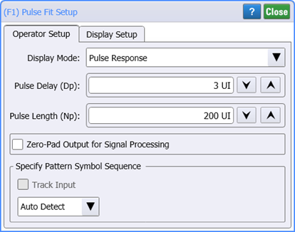
To configure the operator's settings, double click on the operator and select the setup dialog's Operator Setup tab. The following settings are available:
Display Mode
This setting determines the algorithm that Pulse Fit uses to model the system pulse response waveform:
- Pulse Response (default setting) Pulse Fit determines the pulse response waveform from the characteristics of the pseudo-random input pattern which is treated as a series of pulses having different polarities and amplitudes. The pulse fit operator uses the entire pattern and the pulse response is modeled (repeats) at the repetition rate of the pattern. This allows signal processing (for example, CTLE and linear equalization) on the response waveform.
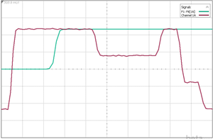
- Step Response fits the pattern to a step waveform.
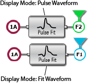
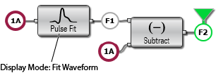
- Fit Waveform allows you to view how well the pulse response models the actual behavior of your waveform. Fit Waveform converts the pulse response back to the ideal input waveform which should closely match the original waveform.
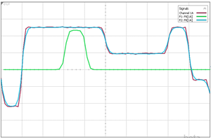
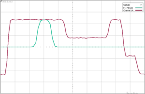
- The first column in the following table simultaneously shows the input waveform (red), Fit Waveform (blue), and Pulse Waveform green. Notice how the input and Fit Waveforms closely match. When creating the second Pulse Fit operator, hold the CTRL key while dragging the first Pulse Fit operator to create and identical copy. Then, click on the copy to select a different Display Mode.
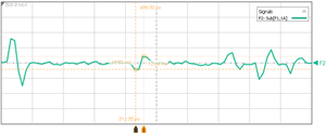
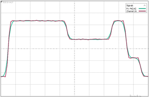
- The table's second column shows how a Subtract operator can be added to view the error between the input waveform and Fit Waveform (green).
| Fit Waveform Compared with Input Waveform | Input, Fit Waveform, and Pulse Response Waveforms |
|---|---|
|
|
|
|
The following figures compare how the Display Mode settings result in different response waveforms. An additional picture shows the Fit Waveform's error waveform which results from adding a Subtract operator to the Pulse Fit Operator. In these pictures, the red trace is the input pattern and the green waveform is the output response.
| Pulse Response | Step Response | Fit Waveform |
|---|---|---|
|
|
|
Pulse Delay (Dp)
Use Pulse Delay to specifies the number of precursor UIs to include in the algorithm to ensure that a portion of the pulse's rising edge is captured. The default value is 3 UI. The minimum setting is 1 UI. The maximum setting is 10 UI.
Pulse Length (Np)
Pulse Length sets the pulse length (duration) to be used when modeling the pulse response. This is the maximum extent that can exist for a single pulse. The default value is 200 UI. The minimum setting is 9 UI. The maximum setting is 1,000 UI.
Zero-Pad Output for Signal Processing
Use Zero-Pad Output in cases where the response waveform goes beyond the Pulse Length. Use this selection when you want to apply filtering or equalization to the pulse response. By default, this setting is cleared.
Specify Pattern Symbol Sequence
By default the pattern symbol sequence is automatically detected (Auto Detect). For situations where the signal is degraded you can manually specify the pattern by selecting a Known Pattern or selecting a Pattern File.