Trigger General Setup Tab
General Trigger Setup
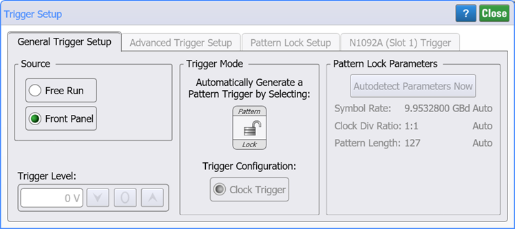
 The General Trigger Setup tab of the Trigger dialog allows you to select the trigger source, level, and bandwidth.
Trigger Source
The Source area always lists the currently available sources based on instrument settings and modules. If you change the trigger source while the acquisition is set to Run (click Run on the menu bar), all newly acquired data erases and overwrites the existing waveforms on the display. If the instrument is stopped, changing the trigger source does not change the display until the instrument is put into run mode. The following selections are available:
- Automatic. FlexDCA automatically selects the trigger source.
- Free Run. Triggers the instrument as soon as the trigger is armed, without having to provide trigger. Free run is asynchronous to the data. Use free-run triggering as an easy way to examine the amplitude of a signal without any timing information. An N1090A module can be used with this setting.
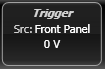
- Front Panel. Trigger the instrument from an external trigger source that is connected to the front-panel Trigger input. This is the most often-used method (as well as the default) source for triggering. An N1090A module can be used with this setting and the Trigger Source will be listed as Clock In on the N1090A Trigger tab.
- CDR. Trigger the instrument from an N1060A precision waveform analyzer module. An N1090A module can be used with this setting and the Trigger Source will be listed as Clock In on the N1090A Trigger tab.
- PTB. Trigger the instrument from a precision timebase. An N1090A module can be used with this setting and the Trigger Source will be listed as Clock In on the N1090A Trigger tab.
Trigger Bandwidth
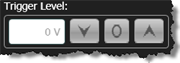 You can adjust the trigger level whenever the Trigger Bandwidth is set to Standard Edge or Filtered Edge. Use this control to define the threshold level that the trigger signal must cross to trigger on the signal. You can enter a level between –1.0V and 1.0V. You can also adjust the trigger threshold level by turning the Trigger Level control knob located on the instrument front panel. When the Divided bandwidth setting is selected, the trigger level is AC coupled and cannot be manually adjusted. The level that you select for the trigger threshold is applied to all trigger sources.
The Trig'd LED indicates the instrument accepted a trigger event. Every time the instrument accepts a trigger event, one data point is sampled. When enough points have been sampled to fill the record length, a trace is completed. The Trig'd LED on the instrument front panel can be used to help determine the trigger thresholds. To do this, move the trigger level in either direction by adjusting the Level in the Trigger dialog or by turning the Trigger Level control knob. When the voltage level crosses the trigger threshold, the LED turns off. Move the trigger level in the other direction to determine the other threshold. You now know what the trigger thresholds are and you can set the trigger level as required by your application. Typically the trigger level is set halfway between the two thresholds. The Armed LED indicates the trigger circuit is armed and waiting for a valid trigger event to occur. A valid trigger event occurs when a signal meets the triggering conditions set in the Trigger dialog.
When the Clock Trigger (50 MHz - 32 GHz) bandwidth is selected, the trigger level is AC coupled and can not be manually adjusted.
On N1000A-PLK instruments, all settings are unavailable (shaded) whenever Pattern Lock is on or Clock bandwidth is selected.
Auto Scale affects the trigger threshold level. Performing Auto Scale will not change the definitions (such as trigger source or bandwidth) set in the Trigger dialog.
Trigger Mode
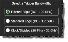 In Oscilloscope and Eye/Mask instrument modes, when the trigger source is set to the front panel and pattern lock is turned off, you can select the bandwidth of the trigger circuitry: Filtered Edge, Edge Trigger, or Clock Trigger.
- Filtered Edge (DC—100 MHz). Use for noisy, low frequency trigger signals, as it can reject high frequency noise. A low-pass filter is added to the trigger path. The DC—100 MHz mode allows for more accurate triggering, but will reduce the effective trigger bandwidth to approximately 100 MHz. The DC—100 MHz mode is DC coupled with an adjustable threshold level from –1.0V to 1.0V. You can select either the rising or falling edge as the trigger edge.
- Edge Trigger (DC—3.2 GHz). Use this default selection for typical measurement applications. It provides excellent performance for trigger signals up to 3.2 GHz. It is DC coupled with an adjustable threshold level from –1.0V to 1.0V. You can select either the rising or falling edge as the trigger edge.
- Clock Trigger (50 MHz—32 GHz). Requires N1000A-PLK. Use this selection for direct or divided triggering on higher frequency signals and is useful with plug-in modules that display signals up to 50 GHz. Because the trigger circuit is AC-coupled, the trigger level can not manually be adjusted and the circuit always triggers at the 0V level. Therefore, the trigger level control is always unavailable (shaded) in this mode. If a trigger signal with a significant DC offset is used, the DC element is blocked. Certain trigger signals that reside at 0V for a long time period and then have an occasional pulse (for example, a pattern generator pattern trigger) will not perform well.
The trigger signal's sensitivity to noise and response time is affected by the bandwidth. Selection of the proper bandwidth is a compromise between the trigger's response to very fast edge speeds and its sensitivity to noise. Noise on the trigger signal can result in inconsistent triggering, which is seen as timing instability (jitter) in the displayed waveform. To reduce the occurrence of inconsistent triggering, reduce the bandwidth of the instrument's trigger circuitry. When pattern lock is turned on, triggering information is automatically detected as the oscilloscope internally generates a pattern lock. Therefore, trigger bandwidth settings are not used and are unavailable.
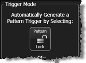
Pattern Lock
Click Pattern Lock to turn pattern triggering on ![]() and off
and off ![]() . Pattern lock cannot be used with an N1090A module.
. Pattern lock cannot be used with an N1090A module.
Test Pattern
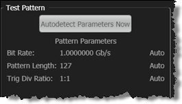 Test Pattern selections are available whenever Pattern Lock is on. Click Autodetect Parameters Now to force the immediate detection of symbol rate, pattern length, and trigger divide ratio. The current pattern lock settings are displayed beneath this button, along with an indication of the detection setting (Auto or Manual) in the Pattern Setup tab of the Trigger dialog.