Fact 2. Model the Test Station in FlexOTO
When you first open FlexOTO, the Hardware Diagram![]() A FlexOTO pane where one models (draws) fiber-optic connections between test setup hardware blocks. pane is displayed. The Hardware Diagram is where you model the physical layout of your Test Station
A FlexOTO pane where one models (draws) fiber-optic connections between test setup hardware blocks. pane is displayed. The Hardware Diagram is where you model the physical layout of your Test Station![]() A manufacturing setup for testing one or more DUT Fixtures. The Test Station includes a Text Executive program to control DUT settings and temperature. so that FlexOTO knows how to control the optical switch routes and DCA-Ms.
A manufacturing setup for testing one or more DUT Fixtures. The Test Station includes a Text Executive program to control DUT settings and temperature. so that FlexOTO knows how to control the optical switch routes and DCA-Ms.
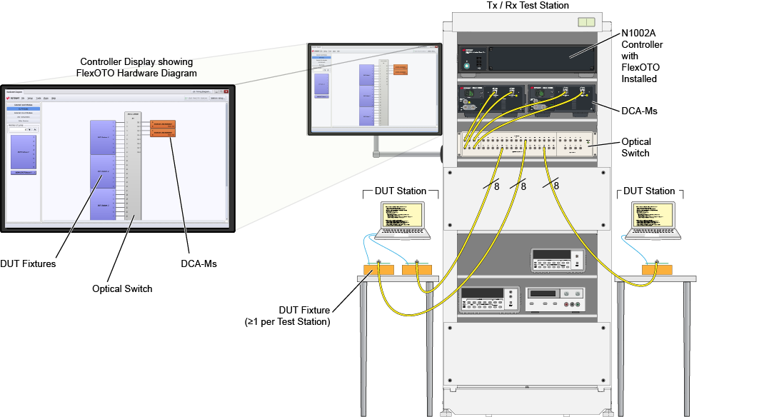
This drawing shows only 3 Test Stations but you can define up to 16! The drawing also shows one switch model and two DCA-M modules. But, you can select from many supported auto-detected equipment.
If your optical switch is not supported, you can write your own optical switch driver to enable FlexOTO to control the switch.