Receiver Setup
Use the System Setup dialog's Receiver Setup tab to connect and configure a supported Receiver to FlexPLL. Use the dialog's Remote DCA fields to connect to the Receiver. Use the Clock Recovery fields to configure CDR settings. CDR settings that you make in this dialog are immediately sent to and configure the Receiver.
Always configure the Receiver 's output using the fields in this dialog. Making these changes directly on the Receiver can cause the FlexPLL test setup to be unstable.
To open this dialog, click Setup > Receiver Setup and select Calibration tab. Or, click the Receiver button located at the bottom of the application.
System Setup
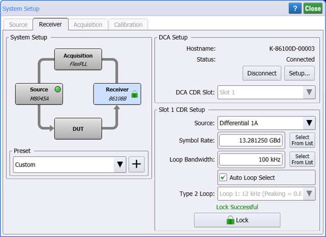
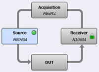 The System Setup diagram illustrates the current equipment hardware connections. You can click the four hardware blocks to move between the System Setup dialog's tabs.
Use the Preset field to save your current System Setup dialog setting so that they can easily and quickly be restored without having to remember or re-enter the individual settings. Click +, and enter a name for your preset. Your preset is now available in the Preset drop down. The following table shows all the settings from the System Setup dialog that are saved in the preset.
FlexPLL comes with several PICe presets as shown in the Supplied FlexPLL System Setup Presets table in this topic. You select one of these presets to automatically configure FlexPLL with the correct settings to use during the calibration step. After the calibration, you load another preset to configure FlexPLL's settings during measurements. Presets are simple XML files so you can view their contents with a text editor.
System Setup Presets
- PCIe Gen1 (81150A-60A Cal)
- PCIe Gen1 (81150A-60A Meas)
- PCIe Gen1 (M8000 Cal)
- PCIe Gen1 (M8000 Meas)
- PCIe Gen2 (81150A-60A Cal)
- PCIe Gen2 (81150A-60A Meas)
- PCIe Gen2 (M8000 Cal)
- PCIe Gen2 (M8000 Meas)
- PCIe Gen3 (81150A-60A Cal)
- PCIe Gen3 (81150A-60A Meas)
- PCIe Gen3 (M8000 Cal)
- PCIe Gen3 (M8000 Meas)
- PCIe Gen4 (81150A-60A Cal)
- PCIe Gen4 (81150A-60A Meas)
- PCIe Gen4 (M8000 Cal)
- PCIe Gen4 (M8000 Meas)
- PCIe Gen5 (81150A-60A Cal)
- PCIe Gen5 (81150A-60A Meas)
- PCIe Gen5 (M8000 Cal)
- PCIe Gen5 (M8000 Meas)
- PCIe Gen6 (81150A-60A Cal)
- PCIe Gen6 (81150A-60A Meas)
- PCIe Gen6 (M8000 Cal)
- PCIe Gen6 (M8000 Meas)
Clock Recovery Setup

Before you can edit the Clock Recovery settings, you must click Connection to connect FlexPLL to the Receiver instrument.
After connecting to the Receiver instrument, make the following selections.
DCA CDR Location
Source
Enter the type signal on the Receiver's input (DUT's output0: differential or single-ended. If your DUT has a differential output, we recommend that you specify differential.
Symbol Rate
Enter the signal's symbol rate. The default setting is 100 MHz. The minimum setting is 1 Hz and the maximum is 500 MHz.
Loop Bandwidth
Enter the desired loop bandwidth used in the Receiver's PLL.
Auto Loop Select

Selecting this setting forces FlexPLL to use the Receiver's CDR Loop Bandwidth and Type 2 Loop settings. For normal operation, Auto is selected, and provides the desired loop characteristic for most measurements. It is recommended that you leave this setting selected.
Type 2 Loop
If Auto Loop Select is cleared, use this field to enter to Type 2 Loop transition frequency used in the receiver's CDR PLL. Normally, you would not want to manually change the loop characteristics. However, some signals have very large low-frequency jitter from either extremely dirty clocks or intentional modulated clocks such as found in SSC (spread spectrum clocking). To ensure the most accurate measurements, FlexPLL allows you to adjust these settings but limits control of the loop dynamics.
![]() Click Lock in this dialog to lock the Receiver's clock recovery. During a Calibration, an adapter replaces the DUT, and the Receiver's CDR does not need to be locked. After a Response calibration completes, FlexPLL automatically locks the Receiver.
Click Lock in this dialog to lock the Receiver's clock recovery. During a Calibration, an adapter replaces the DUT, and the Receiver's CDR does not need to be locked. After a Response calibration completes, FlexPLL automatically locks the Receiver.
When a Response Calibration is performed, the current source and receiver Jitter settings are saved as part of the resulting calibration file. When the calibration file is imported back into FlexPLL, these settings in the calibration file are compared with those in the dialog. If these settings don't match, the calibration is not valid for the current setup. You can resolve this in the Calibrations tab by selecting to copy the settings to the dialog.