Calibrations
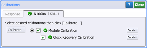
Use the System Setup dialog's Calibration tab to perform the following two calibrations:
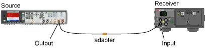
- Response Calibration which removes source and receiver unflatness and identifies single-frequency spurs to avoid during measurement sweeps. (Click the dialog's Response tab). During a Response Calibration, the Source is connected directly to the Receiver, and the Is DUT Installed setting should be cleared. Use the System Setup dialog's DUT tab to specify what the Source's Symbol Rate, Amplitude P-P, Offset, and Symbol Rate are as seen by the Receiver without the DUT.
- Receiver module's clock recovery calibration.
Always calibrate the module before running a Response Calibration.
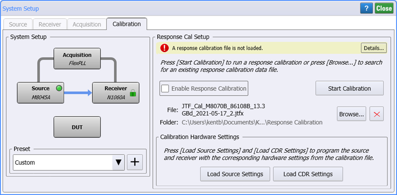
To open this dialog, click Setup > Source Setup and select the Calibration tab. Or, click the Calibration button located at the bottom of the application.
System Setup
 The System Setup diagram illustrates the current equipment hardware connections. You can click the four hardware blocks to move between the System Setup dialog's tabs.
Use the Preset field to save your current System Setup dialog setting so that they can easily and quickly be restored without having to remember or re-enter the individual settings. Click +, and enter a name for your preset. Your preset is now available in the Preset drop down. The following table shows all the settings from the System Setup dialog that are saved in the preset.
FlexPLL comes with several PICe presets as shown in the Supplied FlexPLL System Setup Presets table in this topic. You select one of these presets to automatically configure FlexPLL with the correct settings to use during the calibration step. After the calibration, you load another preset to configure FlexPLL's settings during measurements. Presets are simple XML files so you can view their contents with a text editor.
System Setup Presets
- PCIe Gen1 (81150A-60A Cal)
- PCIe Gen1 (81150A-60A Meas)
- PCIe Gen1 (M8000 Cal)
- PCIe Gen1 (M8000 Meas)
- PCIe Gen2 (81150A-60A Cal)
- PCIe Gen2 (81150A-60A Meas)
- PCIe Gen2 (M8000 Cal)
- PCIe Gen2 (M8000 Meas)
- PCIe Gen3 (81150A-60A Cal)
- PCIe Gen3 (81150A-60A Meas)
- PCIe Gen3 (M8000 Cal)
- PCIe Gen3 (M8000 Meas)
- PCIe Gen4 (81150A-60A Cal)
- PCIe Gen4 (81150A-60A Meas)
- PCIe Gen4 (M8000 Cal)
- PCIe Gen4 (M8000 Meas)
- PCIe Gen5 (81150A-60A Cal)
- PCIe Gen5 (81150A-60A Meas)
- PCIe Gen5 (M8000 Cal)
- PCIe Gen5 (M8000 Meas)
- PCIe Gen6 (81150A-60A Cal)
- PCIe Gen6 (81150A-60A Meas)
- PCIe Gen6 (M8000 Cal)
- PCIe Gen6 (M8000 Meas)
Response Calibration
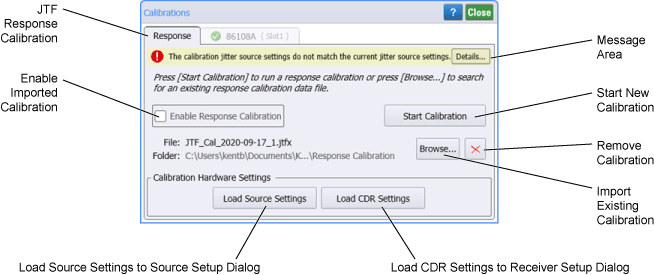
The following picture identifies the dialog items for the Response calibration. To perform a new calibrations, click Start Calibration. The remaining information in the tab relates to the state of the currently loaded calibration. The message area show the state of the Response calibration with these messages:
| Message | Do this... |
|---|---|
| A response calibration is not loaded. | Click Start Calibration to begin a new calibration or click Browse to import a previously saved calibration. |
| Created: <date> | A valid calibration is loaded. Select Enable Response Calibration to use the calibration data or click Start Calibration to create a new calibration. You can also click Browse to import a previously saved calibration. |
| The calibration jitter source setting do not match the current jitter source settings. | Calibration files include Jitter settings saved from the Source Setup dialog and Clock Recovery settings saved from the Receiver Setup dialog. To ensure the calibration validity, click Load Source Settings and Load CDR Settings to copy the settings from the calibration file to the dialogs. Or, click Start Calibration to replace the current calibration data. |
| Button States | Settings |
|---|---|

|
Loads CDR settings into the Receiver Setup dialog |

|
Calibration file settings match Receiver Setup dialog |

|
Loads Source settings into the Source Setup dialog |

|
Calibration file settings match Source Setup dialog |
Calibration Files
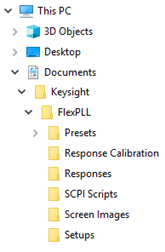
Each time that a Response Calibration is performed, FlexPLL automatically saves a calibration file (*.jtfx). You can load a saved calibration file into this dialog, saving you time when making measurements. Calibrations are valid for a specific test equipment setup (as noted below) and temperature conditions. Be sure to give custom names to your calibration files to make them easier to identify. Calibration file are saved in the FlexPLL's \Response Calibration folder:
C:\Users\user-name\Documents\Keysight\FlexPLL\Response Calibration
A Response Calibration is valid only when both of the following current conditions are true:
- Test setup hardware matches the hardware used at the time that the calibration was created.
- Source and Receiver settings match the settings used at the time that the calibration was created. If the settings match for the current calibration, the Load Source Settings and Load CDR Settings are not active (grayed out) and the calibration is valid. If the settings do not match, these buttons are active, and you can click them to copy the settings from the calibration file to the dialogs.
Since calibration data is automatically saved in a Response file (.rspx), calibration files are not needed to view these files.
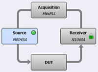
During a Response Calibration, the JTF source is connected directly to the JTF receiver. In this situation, the receiver's CDR does not need to be locked. However, FlexPLL will automatically lock the receiver's CDR before performing measurements.
To create a new Response Calibration
- In the test setup, place an adapter between the source and the receiver cables where the DUT would normally be connected. This is shown in following figure.
- Ensure that the settings in the Source Setup tab are correct and that Output Enable is selected.
- Ensure that the settings in the Receiver Setup tab are correct.
- Click Start Calibration.
-
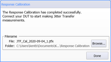 When the Calibration completes and this dialog appears:
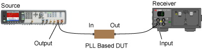
 - Replace the adapter with your DUT in the test setup and turn the DUT on.
- Click Done to close the dialog. After a short pause, FlexPLL prepares the measurement and attempts to lock the Receiver's clock recovery. Shortly thereafter the calibrated JTF measurement sweeps begins.
- If the DUT's output symbol rate is different than the DUT's input symbol rate:
- Open the System Setup dialog's Receiver tab and enter the correct Symbol Rate for when the DUT is in the test setup.
- Click the dialog's Lock button
 to lock the receiver's clock recovery to the correct symbol rate.
For more information about situations where the DUT's input and output symbol rates differ, read User Tips!.
Receiver Module Calibration
| Icon | Description |
|---|---|
| Calibration is selected | |
| Calibration is unselected | |
| Calibrations are partially selected | |
|
|
Calibration is current |
|
|
Calibration is recommended |
|
|
Calibration has never been performed |
Module calibration consists of a clock recovery calibration that does not require any external equipment setup. Always remove or disable all inputs to the module. FlexPLL automatically disables the source instrument's output during a clock recovery calibration.
A module calibration is recommended when:
- DCA-X (or DCA-M) power has been cycled
- Module has been removed and then reinserted since the last calibration
- DCA-X temperature change exceeds 5°C compared to the temperature of the last module calibration (ΔT > 5°C)
- Time since the last calibration has exceeded 10 hours
FlexPLL does not perform a module's vertical calibration. Although the DUTs output is connected to the inputs channels of an N1060A module, the signal is routed just inside the module's front panel to the clock recovery circuits. Therefore the channel path (vertical calibration) is not used and does not need to be calibrated for FlexPLL. Only the module's clock recovery path needs calibration.
To avoid corrupting module memory, do not remove or insert any module from the DCA-X during a calibration. If a message indicates that a module has corrupt contents, refer to Module Memory Recovery in FlexDCA's help.
Re-seating the module into the DCA-X may affect the electrical connections, which in turn affects the data sampling process.