Source Setup
Use the System Setup dialog's Source Setup tab to connect and configure FlexPLL's supported Source. Use the dialog's Jitter Source Setup fields to connect to the Source. Use the dialog's Channel Setup fields to configure the connected Source's jitter for the test. Jitter settings that you make in this dialog are immediately sent to and configure the Source instrument.
The Channel Setup fields in this dialog change depending on whether the Source is a supported Keysight pulse function arbitrary noise generator or high performance BERT.
Always configure the Source's output using the fields in this dialog. Making these changes directly on the Source can cause the FlexPLL test setup to be unstable.
To open this dialog, click Setup > Source Setup and select Source tab. Or, click the Source button located at the bottom of the application.
System Setup
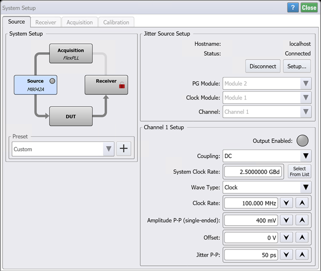
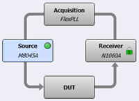 The System Setup diagram illustrates the current equipment hardware connections. You can click the four hardware blocks to move between the System Setup dialog's tabs.
Use the Preset field to save your current System Setup dialog setting so that they can easily and quickly be restored without having to remember or re-enter the individual settings. Click +, and enter a name for your preset. Your preset is now available in the Preset drop down. The following table shows all the settings from the System Setup dialog that are saved in the preset.
FlexPLL comes with several PICe presets as shown in the Supplied FlexPLL System Setup Presets table in this topic. You select one of these presets to automatically configure FlexPLL with the correct settings to use during the calibration step. After the calibration, you load another preset to configure FlexPLL's settings during measurements. Presets are simple XML files so you can view their contents with a text editor.
| Dialog Settings | ||
|---|---|---|
| Source Tab | Receiver Tab | Acquisition Tab |
| System Clock Rate | Symbol Rate | Start Frequency |
| Wave Type | Auto Loop Select | Stop Frequency |
| Clock Rate | Type 2 Loop | Points / Decade |
| Pattern | Averaging | |
| Symbol Rate | ||
| Amplitude P-P (single ended) | ||
| Offset | ||
| Jitter Amplitude P-P | ||
| Output Coupling | ||
System Setup Presets
- PCIe Gen1 (81150A-60A Cal)
- PCIe Gen1 (81150A-60A Meas)
- PCIe Gen1 (M8000 Cal)
- PCIe Gen1 (M8000 Meas)
- PCIe Gen2 (81150A-60A Cal)
- PCIe Gen2 (81150A-60A Meas)
- PCIe Gen2 (M8000 Cal)
- PCIe Gen2 (M8000 Meas)
- PCIe Gen3 (81150A-60A Cal)
- PCIe Gen3 (81150A-60A Meas)
- PCIe Gen3 (M8000 Cal)
- PCIe Gen3 (M8000 Meas)
- PCIe Gen4 (81150A-60A Cal)
- PCIe Gen4 (81150A-60A Meas)
- PCIe Gen4 (M8000 Cal)
- PCIe Gen4 (M8000 Meas)
- PCIe Gen5 (81150A-60A Cal)
- PCIe Gen5 (81150A-60A Meas)
- PCIe Gen5 (M8000 Cal)
- PCIe Gen5 (M8000 Meas)
- PCIe Gen6 (81150A-60A Cal)
- PCIe Gen6 (81150A-60A Meas)
- PCIe Gen6 (M8000 Cal)
- PCIe Gen6 (M8000 Meas)
Jitter Source Setup
Click Setup to open the Source Connection Setup dialog. Make the Source connection settings, and then click Connect to Source.

Select the Source's Module and output Channel, if available. The Module selection is only available on a M8000-series BERTs that have more than one BERT module.
Channel Setup
The following steps show how to configure the Channel Setup settings.
- If the Source is an 81150A or 81160A, enter the Clock Rate in Hz. If the DUT expects a data input, set the clock rate to half the data rate. For example, if the DUT's data input should be 200 MHz, set the 81160A clock output is 100 MHz. With two symbols per clock cycle (one and zero), the equivalent data rate is double the clock frequency.
- If the Source is an M8000-series BERT:
- Set the Coupling to AC or DC.
- If you set the Wave Type to Clock:
- Enter the Clock Rate in Hz which is the Source's output clock to your DUT.
- Enter the System Clock Rate in Hz.
- If you set the Wave Type to Data:
- Select the data Format: NZR or PAM4.
- For Pattern, select an available PRBS or Clock.
- Enter the System Clock Rate in Hz, which automatically sets the Symbol Rate. The Symbol Rate is the Source's output to your DUT and is locked to the value specified for the System Clock Rate.
- Enter the signal's Amplitude P-P (single ended).
- Enter the signal's amplitude Offset.
- Enter the Jitter P-P in seconds.
- Select Output Enable to turn the source's output on.
The System Clock Rate is the bit frequency of the M8000-series BERT's internal pattern generator, and Clock Rate is the frequency of the generated clock output signal. FlexPLL forces the Clock Rate to be an integer sub-rate of the System Clock Rate. The output clock is created by a sequence of 0s and 1s from the BERT's internal pattern generator. For example, if the System Clock Rate is 10 GHz and the Clock Rate is 2.5 GHz, the clock signal is build from a repeated 0011 bit stream played at 10 GHz.
For best measurement results, ensure that the System Clock Rate is the same frequency during the calibration as is used during the measurements.
Ensure that the amplitude is within the specification for the Receiver's input connector for the test setup Calibration and for the DUT during measurements. Do not change this setting after the Calibration.
When connecting the RF cable between the Source's output and the DUT's input, be aware that some PCI Express devices do not include an "on board" termination. In this case, if FlexPLL's default Source amplitude and offset settings are decreased, you may need to connect a 6 dB matching attenuator on the output of the Source.
It is recommended that you set the Jitter Amplitude P-P as high as possible to improve the measurement signal-to-noise ratio. However, if jitter amplitude is set too high the DUT's or the measurement receiver's clock data recovery could lose lock. For example, PCIe DUTs take a 100 MHz clock input and multiply it up to a multiple GB data output. This requires that the source jitter's peak-to-peak amplitude be kept below a fraction of that multiplied up data rate clock, not the input slower 100 MHz rate.