About CSI-RS MIMO Info Table (LTE-Advanced)
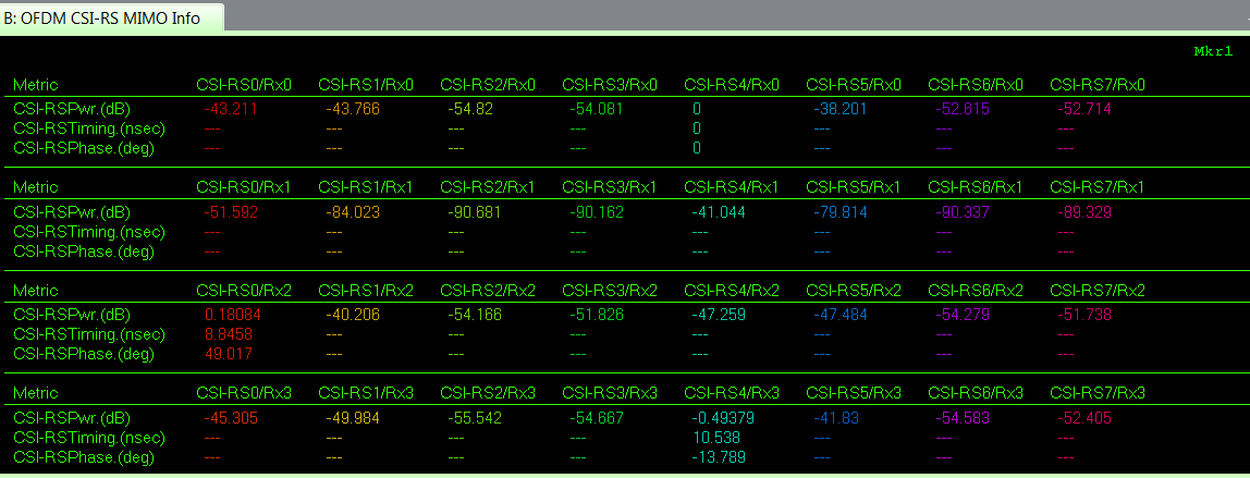
shows information about the CSI-RS Channel State Information Reference Signal antenna port transmissions detected by the demodulator. This summary table includes power, phase and timing information for each CSI channel state information-RS/Channel path. This result table should be as below:
|
Metric |
Description |
|---|---|
| CSI-RSPwr (dB) | Average (RMS) CSI-RS signal power |
| CSI-RSTiming (nsec) | CSI-RS timing error |
| CSI-RSPhase (deg) | Average (RMS) CSI-RS phase error |
Each row of power, timing and phase information is input channel. Each column is a CSI-RS port.
Each group of data is uniquely numbered (CSI-RSn/Rxn), where:
CSI-RSn = antenna port number
Rxn = input channel number
About CSI-RS
In LTE Long Term Evolution-A MIMO measurements, currently we can get MIMO information based on three different kinds of reference signals. The first one is the CRS (cell specific reference signal), which provides the power/phase/timing difference measurement on up to 4 different CRS layers (antenna ports). The second kind of reference signal is the UE User Equipment (e.g. cell phone)-DMRS (user specific demodulation reference signal), which provides the DMRS weights per user or per RB Resource Block on different DMRS antenna ports. The third kind of reference signal is the CSI-RS (Channel State Information Reference Signal). The CSI-RS Info Table reports a smaller set of information (power, timing, and phase) than CRS. However, unlike CRS, the CSI-RS provides channel estimation for up to 8 layers (antenna ports), which can be very important to users who need more precise channel performance.
See Also