Antenna Layout (5G NR/5G-Advanced)
The Antenna Layout parameter group configures the geometry, or the X,Y,Z coordinates, of the antenna elements in the array. In some systems, antenna arrays are divided into subarrays, grouping multiple elements into each subarray. In VSA, each subarray connects to a specific RF Radio Frequency: A generic term for radio-based technologies, operating between the Low Frequency range (30k Hz) and the Extra High Frequency range (300 GHz). input port. For example, an array with 96 elements and 32 subarrays (3 elements per subarray) results in 32 RF inputs to the VSA. The VSA software can support up to 64 input ports.
selects between rectangular and user-defined antenna layouts, which is used with Antenna Pattern, Antenna Detection Threshold, Beam Patterns Include and Beam Weights to compute the simulated Beam Pattern.
Rectangular - (Default) Selects a rectangular antenna layout as defined by the 3GPP TR 38.901 specification, with selectable number and spacing of the array of groups and panels using the Configure Rectangular Array dialog. A summary of the configured rectangular array is displayed for convenience.
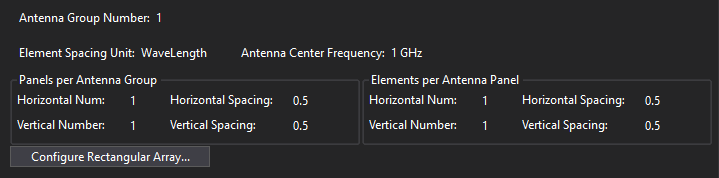
Configure Rectangular Array - Opens a Rectangular Antenna Array dialog to configure the panels per antenna group and elements per panel. The element spacing can be specified in either wavelength or meters.
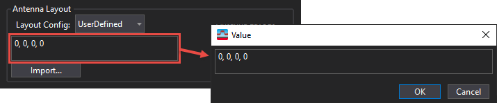
User Defined - Manually enter an array of antenna element positions or import a user-defined antenna layout file.
Manual entry - Double-click the antenna layout coordinates area to open a Value dialog.
Enter the antenna element positions as (index, x, y, z), separated by commas. The index values correspond to VSA input channels, and x,y,z are the element coordinates in meters. You can enter the index value for each antenna element in the array, or leave them as "0" and let the VSA software automatically apply index values. Enter the values continuously, without line returns. A line return will be automatically inserted for each antenna element when OK is clicked.
The following example is for a 2-dimensional YZ-plane antenna layout (X = 0 for all elements). The array consists of 4 elements along the Y-axis (horizontal spread) and 2 elements along the Y-axis (vertical stack), for a total of 8 elements.
For dual-polarized antenna arrays, the first half of the index values in the user input antenna layout (e.g., Index 0-3) is for polarization 1 and the second half (e.g., Index 4-7) is for polarization 2.
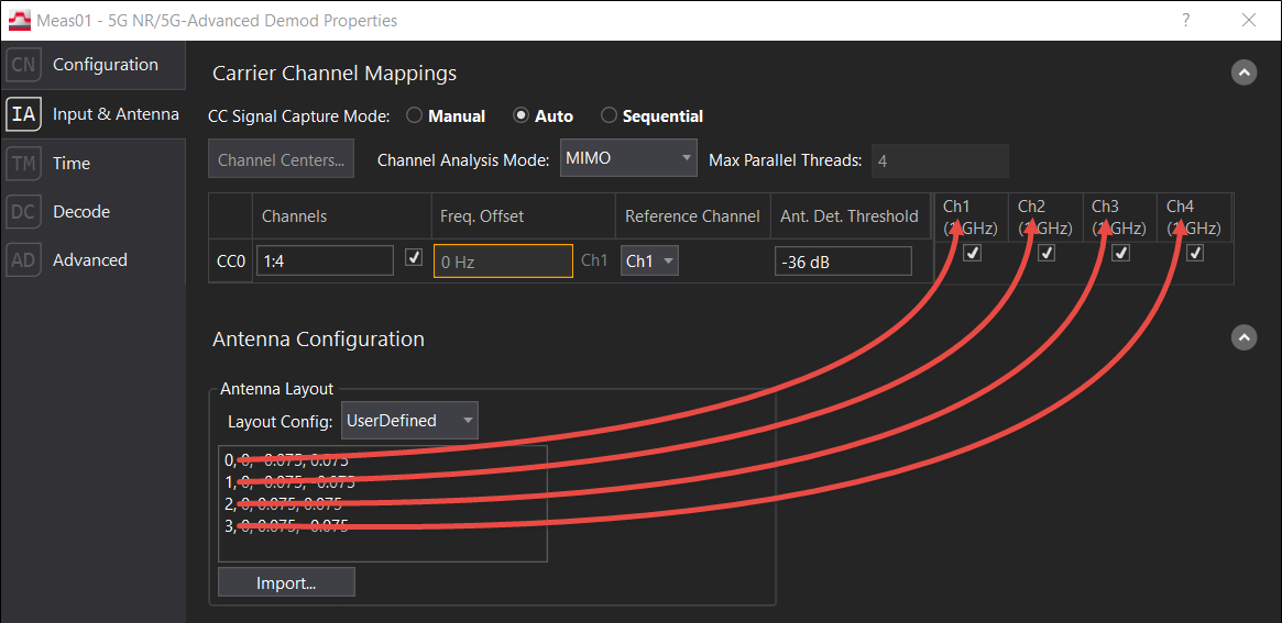
Antenna Layout Index 0 corresponds to Ch1, Index 1 to Ch2, Index 2 to Ch3, Index 3 to Ch4, and so forth.
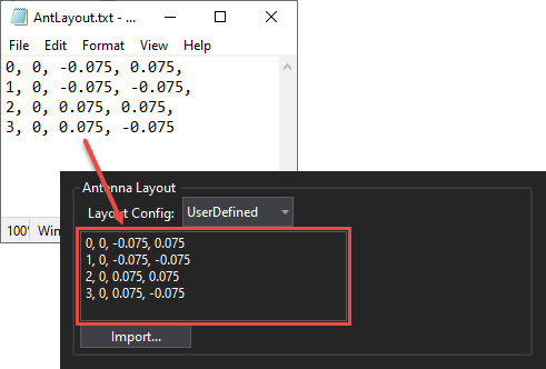
Import - Click the Import button to open a dialog to select a user-supplied antenna layout file.
The antenna layout file can be in .txt or .csv format, with antenna element positions defined as (index, x, y, z), separated by commas. The index values correspond to VSA input channels, and x,y,z are the element coordinates in meters. You can enter the index value for each antenna element in the array, or leave them as "0" and let the VSA software automatically apply index values. Enter the values with or without line returns between antenna elements. A line return will be automatically inserted for each antenna element if needed.
For dual-polarized antenna arrays, the first half of the index values in the file correspond to polarization 1 and the second half correspond to polarization 2. The first and second halves should have the same coordinates in the file.
See Also