Click ![]() on
the Plot Toolbar
to turn ON and OFF both the Eye Mask and the PASS
| FAIL text.
on
the Plot Toolbar
to turn ON and OFF both the Eye Mask and the PASS
| FAIL text.
The PASS | FAIL text (alone) can be turned ON and OFF with a User Preference. Learn how.
Use mask testing to verify that a displayed Eye Diagram complies with an industry-standard waveform shape. A mask is a template that consists of pass/fail regions on the PLTS display screen. The input waveform must remain outside the fail regions in order to comply with the industry standard. Any acquired data point that falls inside a fail region appears in red and is logged as a mask test failure.
In this topic:
Other Eye Diagram topics
By default, limit line PASS | FAIL testing is ON. The Meas tab displays running totals of the number of waveforms sampled and number of failed samples.
Click ![]() on
the Plot Toolbar
to turn ON and OFF both the Eye Mask and the PASS
| FAIL text.
on
the Plot Toolbar
to turn ON and OFF both the Eye Mask and the PASS
| FAIL text.
The PASS | FAIL text (alone) can be turned ON and OFF with a User Preference. Learn how.
There are two ways to create an Eye mask in PLTS:
Limit Mask Definition Pane - Simple with limited settings (shown below).
Define Eye Mask Dialog - More comprehensive method.
Important Note: The ONLY way to apply an Eye Mask to a Eye Diagram is using the Import button on the Limit Mask Definition Pane, regardless of the method that was used to create or edit the Eye Mask.
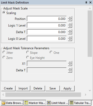
Use the Limit Mask Definition pane to quickly create a simple Eye diagram mask for Pass/Fail testing.
In this dialog, you can also Import a previously-defined Eye Mask.
1. On the Limit Mask Definition Pane, click Create
Refer to this diagram for the following descriptions:
|
Click to import a mask with one of the following file formats:
PLTS |
*.xml |
Create, import, and save. |
DCA |
*.msk |
Import only. |
FlexDCA |
*.mskx |
Import only. Supports NRZ and PAM4. |
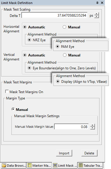
Importing an NRZ mask or drawing/selecting a PAM4 eye diagram plot changes the appearance and available functions of the Limit Mask Definition panel. Learn more above.
PLTS installs a library of FlexDCA eye mask files (*.mskx) on your PC in ...\Documents\Keysight PLTS 2023 (64-bit)\EyeMasks\FlexDCA_Masks. Most of the folders within this library provide NRZ mask files. PAM4 mask files reside in the "Open Eye" folder.
Note: Once a mask
is imported, it is immediately applied to the selected plot. If it does
not appear, click ![]() on the Plot Toolbar
to turn ON and OFF both the Eye Mask and the PASS
| FAIL text.
on the Plot Toolbar
to turn ON and OFF both the Eye Mask and the PASS
| FAIL text.
After opening a mask, PLTS positions the mask parameters as follows:
Mask position - the mask’s horizontal center is aligned to the plot horizontal center
Logic 1 level - this value is read from Automated Eye Diagram Measurement Results.
Logic 0 level - this value is read from Automated Eye Diagram Measurement Results.
When the mask test starts, PLTS automatically aligns the mask to the waveform data on the display graticule. If there is more than one eye diagram on the display graticule, the mask aligns to the first zero-crossing point.
Use the Vertical scale controls to adjust the display for optimal viewing. Learn more.
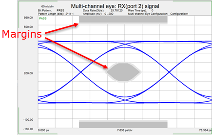
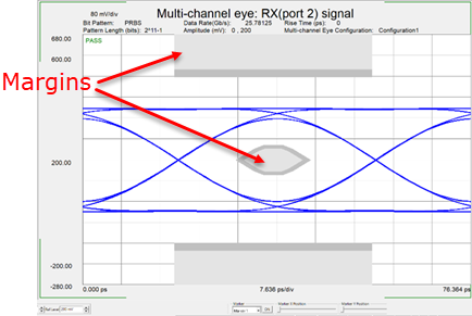
Mask margins are used to determine the margin of compliance for a standard or scaled mask. Margins indicate areas that are to contain a specified number of hits (violations within the mask region) in order to comply with testing standards. You can use this information to determine by what level the waveform begins to fail to comply with industry standards. Mask regions are shown in dark gray, and mask margins are shown in light gray. Any acquired data point that falls inside a mask margin appears in red. You can specify positive or negative margins:
Positive margins determine how much larger you will be able to increase the mask size before violations occur. Enter between –100% and +100% linear change in mask size.
Negative margins determine how much smaller you have to decrease the mask size before violations no longer occur. Enter between –100% and +100% linear change in mask size.
Positive Margin Value |
Negative Margin Value |
 |
 |
There are two ways to create a new mask in PLTS:
Limit Mask Definition Pane - Simple with limited settings (shown above).
The following Define Eye Mask Dialog -is a more comprehensive method.
Click Tools, then Define Eye Mask
Define the shape and values of the Eye Diagram Mask. Measured values outside the shaded area will be flagged as a failures. 1. Select Defining ModeChoose the method of defining the diagram:
2. Define the Top, Middle, and Bottom of MaskTop Region All eye data should be less than ...(mv). The maximum expected value. Voltages exceeding this value will fail. Middle Region The size and shape of the Eye diagram Mask.
Bottom Region All data should be greater than ... Enter the minimum expected value. Levels below this value will fail. 3. Save and RecallStores the Eye Diagram Mask to an *.xml file, or Recall a previously created Eye Diagram Mask for editing.
Import this Eye Mask using the Limit / Mask Definition pane.
|