Setting Up, Calibrating, and Making Measurements using the TDR-Based
PLTS
This topic guides you through the following:
Overview
PLTS supports the TDR-based PLTS hardware using coaxial test cables.
You will need four coaxial test cables for the TDR-based PLTS measurements.
For the Keysight
DCA 86100A/B/C, we recommend you use:
For the Tektronix CSA8000 and TDS8000,
we recommend you use:
Four 3.5 mm (male-male) cables (Keysight part number
8120-4948) -OR-
Four 3.5 mm (male-female) cables (such as the Keysight
N4419A-B20) with a 3.5 mm (male-male) adapter (Keysight part number
1250-1748)
You also need the following calibration standards to perform the TDR
calibration. Different standards are required depending on the TDR-based
PLTS hardware and the desired calibration type.
Required 3.5mm (SMA) Calibration Standards
TDR
System |
Module
Calibration |
Calibration
For
Single-Ended Measurements |
Calibration
for Differential Measurements |
Reference
Plane Cal Only |
Normalization
plus Reference Plane Cal |
Reference
Plane Cal Only |
Normalization
plus Reference Plane Cal |
Keysight 86100A/B/C |
1
50W
Load |
1
Thru |
1
50W
Load
1 Short
1 Thru |
2
Thrus |
2
50W Loads
2 Shorts
2 Thrus |
Tektronix CSA8000/
TDS8000 |
2
50W
Loads |
1
Thru |
Not
Applicable |
2
Thrus |
Not
Applicable |
Recommended Keysight Part Numbers:
Loads, 3.5mm (f), 1250-2151; 3.5 mm (m) 1810-0118
Shorts, 3.5mm (f), 1250-2152; 3.5mm (m) 1250-2153
Thrus, 3.5mm (f-f), 5061-5311;
Keysight Probe Model Numbers:
CAUTION
Avoiding
ESD Damage to TDR Plug-In Modules
The TDR input connectors are very sensitive to electrostatic
discharge (ESD). When you connect a device or cable that is not
fully discharged to the input connector, you risk damage to the
module and expensive instrument repairs. Refer to your TDR documentation
for detailed information regarding ESD susceptibility. |
Note:
Improved TDR Accuracy in Frequency
Domain
The TDR pulse or step stimulus has a finite rise time of about
40 ps. When TDR measurements are viewed in the Frequency Domain,
the finite rise time is translated into Loss.
To allow this added accuracy, click Tools,
then Improved TDR Cal Correction
before calibrating in TDR mode. |
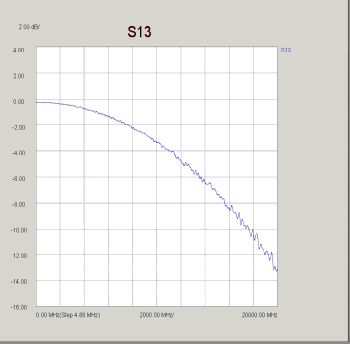
Before PLTS 4.2
The image to the right MISTAKENLY indicates a 14 dB loss through
a very short (2 cm) Thru path. |
|
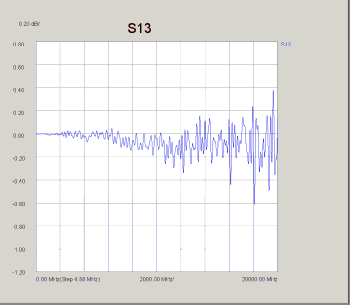
Beginning with PLTS 4.2
The image to the right shows indicates an accurate view of very
minimal loss through the same 2 cm Thru path.
A Response cal is performed which includes the finite rise time
of the TDR stimulus and is removed when viewing Frequency Domain
plots. |
|
Launching the Startup Wizard
The Startup Wizard is displayed when the PLTS application is started.
It is also displayed anytime a new measurement is initiated, such
as after selecting New
from the File
menu, or clicking on the new file
icon on the toolbar. Learn more
about the Startup Wizard.
Set Up the TDR
This dialog box allows you to set the TDR parameters for the calibration
and measurement. Each of these parameters is described in the following
table TDR Parameter
Descriptions.
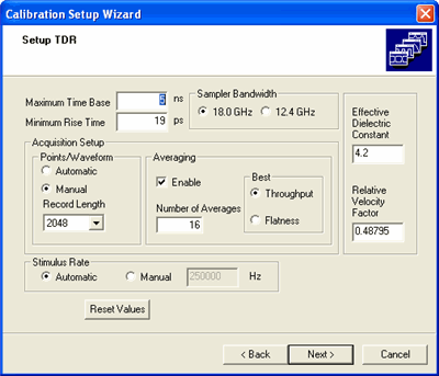
This wizard screen is initially displayed with default values for each
entry. You may accept or modify these values. Modifying some of these
values directly may also modify other associated values interactively.
For example, when changing the Effective
Dielectric Constant, the Relative
Velocity Factor will change appropriately.
Reset
Values returns all selections and values to their default
value.
TDR Parameter Descriptions
Parameter |
Description |
Maximum Time Base |
Sets
the desired measurement range in nanoseconds.The default setting
is 5 ns. Typically the time base should be set to 2.5-3 times the
electrical length of the DUT. Note: reflection measurements are
"round trip". |
Minimum Rise Time |
Sets
the rise time of normalized measurements in picoseconds. This
is a function of normalization and is available to only the Keysight
86100-based TDR system. |
Sampler Bandwidth |
Sets
the Keysight 86100-based TDR system receiver to either a 18.0 GHz bandwidth
(which gives the highest fidelity and the fastest response time)
or a 12.4 GHz
bandwidth (which gives the best sensitivity by reducing the noise).
This bandwidth is set at 20 GHz for other TDR systems. |
Points/Waveform |
Sets
the number of points for a waveform. The more points, more accurate
and slower the measurement.
Automatic -
allows the TDR to select the record length for the input waveform.
The TDR selects a record length that optimizes the amount of acquired
data and the display update rate. This is available only with
the Keysight 86100-based TDR system.
Manual
- allows you to define a record length from a list of points.
Record Length - allows you to select
the number of points from a list. The number of data points
that are available depends of the TDR system:
For the Keysight DCA 86100
16, 32, 64, 128,
256, 512, 1024, 2048, 4096 in
addition, 8192 and 16384
data points are available with DCA firmware 8.0 or higher.
For the Tektronix CSA8000
and TDS8000:
20, 50, 100,
250, 500, 1000, 2000, or 4000. |
Averaging |
Enable - turns
the trace averaging on and off. Number of Averages
sets the number of sweeps to be
averaged. Increasing the number of averages improves the signal-to-noise
ratio at the cost of increased measurement time.
Best Throughput - allows you to view the waveform
as it is acquired. The TDR displays any noise and feed through
error on the signal. It has a faster measurement time. This is
available to only the Keysight 86100-based TDR system.
Best Flatness - turns on the feed through compensation
circuit which reduces the amount of feed through error. This is
useful when the measurement time base is in the 1ms
range or greater. It has a slower measurement time. This is available
to only the Keysight 86100-based TDR system. |
Effective Dielectric Constant |
Specifies
the dielectric constant for your transmission medium. If the DUT
is an embedded stripline printed circuit board trace, then the
same material is on each side of the DUT and the effective dielectric
constant is simply the value of the dielectric material. This
device configuration is known as a "homogenous dielectric
system". If the DUT is a microstrip printed circuit board
trace with one side exposed to air, then the effective dielectric
constant is a combination of air dielectric (1.0) and the dielectric
material. This device configuration is known as a "nonhomogenous
dielectric system". If the DUT is a complex channel consisting
of PCB traces, connectors, vias and/or cables, then the effective
dielectric constant will also be complex. |
Relative Velocity Factor |
Specifies
the relative velocity for your transmission medium. Some velocity
factor (VF) examples are: Air VF=1.000, Surface traces VF=0.53146,
Buried Traces in er~4.3: VF=0.48795 |
When the Setup TDR
dialog box values are correct, click Next
> to continue.
Select the Calibration and
Measurement Parameters
The Select Calibration and Measurement
Parameters dialog box is displayed. The left side of the dialog
box lists all 16 of the available single-ended measurements. The right
side of the dialog box lists all 16 of the available differential measurements.
Note:
If you are using only one TDR module, your available measurements
will be limited only eight parameters will be available.
For example, if your 54754A TDR module is installed in the left
slot, you will only be able to measure four single-ended parameters
(T11, T12, T21, and T22) and four differential parameters (TDD11,
TDC11, TCD11, and TCC11). |
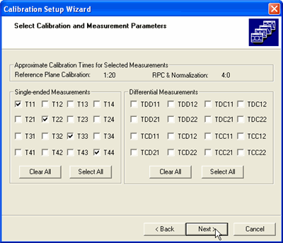
When a measurement is selected, it has a check in the check box for
the corresponding measurement. However, you may not need or desire data
for all 32 parameters (16 single-ended and 16 differential parameters).
As a general rule, the more parameters that you select, the longer the
calibration and the measurement takes to perform. The following
provides a tool for estimating calibration times for each selected parameter.
Approximate
Calibration Times for Single-Ended Parameters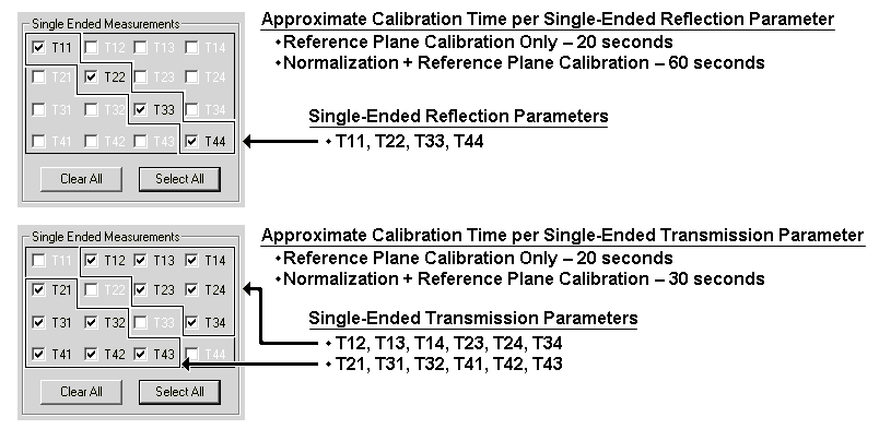
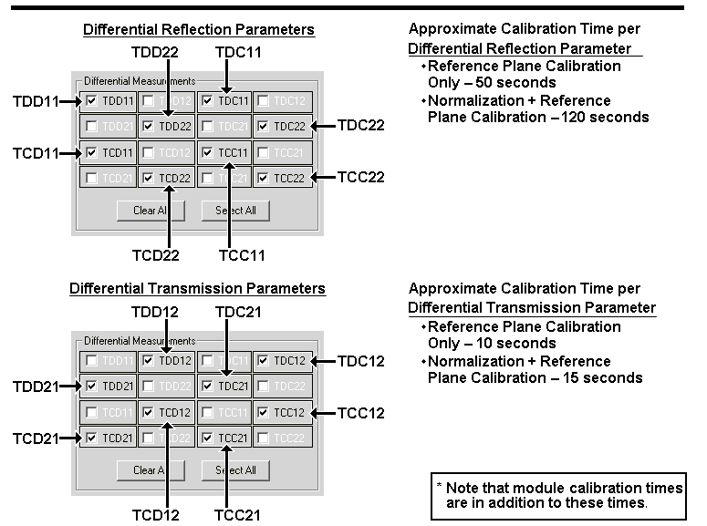
Leave all parameters selected for this example exercise and then click
the Next > button.
Performing a Calibration
The PLTS software adds value and capability to both Keysight and Tektronix
TDR systems by automating the calibration process which saves time, reduces
the chance of calibration errors, eliminates tedious procedures, and improves
the calibration results. The PLTS calibration process includes:
Selecting
a calibration kit and defining the calibration file name.
This step uses the Select
Calibration Kit and Filename dialog box to select the calibration
standards and connectors that are used during the calibration process.
The file name that the calibration information is saved to is also
defined.
Defining
a calibration kit. This optional step allows you
to define a calibration kit if none of the pre-defined calibration
kits match your calibration needs.
Choosing
the calibration type. This step uses the Calibrate TDR and Modules wizard window
to define the type of TDR calibration that will be performed, either
a "Reference Plane Calibration Only" or a "Normalization
and Reference Plane Calibration".
Performing
the calibration for the TDR modules. This step uses the
Calibrate TDR and
Modules wizard window to perform the calibration for the modules
within your system.
Setting
the reference plane at the end of the cables. This step
uses the Calibrate
TDR and Modules wizard window to perform the standards calibrations,
either the Reference Plane Calibration Only or the Normalization and
Reference Plane Calibration.
Once the Next >
button in the Select
Calibration and Measurement Parameters dialog box is selected,
the Select Calibration
Kit and Filename wizard screen is displayed.
Note: At any time
you can initiate a re-calibration of your measurement hardware,
Characterize an
Adapter, or Edit a Cal Kit. Select Utilities, then select your hardware
setup.
Select a Calibration
Kit and Define the Calibration File Name
The PLTS software has five default TDR calibration kits. It also stores
the calibration kit information.
Pre-Defined TDR Calibration
Kits
Name |
Description |
85052D-M |
85052D male cal kit |
85052D-F |
85052D female cal kit |
Default
SMA |
TDR cal kit with female SMA thru |
Default_3.5mm |
TDR cal kit with 3.5mm Connector
Saver |
N1020A-K05 |
N1020A TDR Probe cal kit |
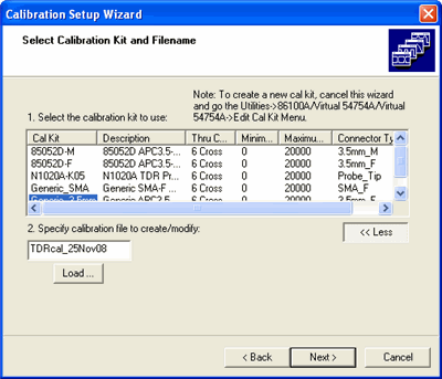
Select
the calibration kit to use: The PLTS software has several calibration
kits already defined for the TDR calibration. All of these calibration
kits are listed in the Select
the calibration kit to use: list. PLTS is set to the Default 3.5mm selection.
If the calibration kits listed in the Select the calibration
kit to use: list area do not match your calibration kit, you may
define a new calibration kit to meet your requirements. Refer to Define
a Calibration Kit.
Specify calibration
file to create/modify: Specify the file that you will use to
save the calibration data. The text box displays a default calibration
file name based on the current date. It uses the string "TDRcal_"
followed by the current date. You may enter another file name if you
like. This calibration file name is used as a base name for saving
calibration files on the PC and on the Keysight 86100-based TDR (if
this TDR is being used).
Files Stored on the
PC This calibration file name is used as a base
name for saving calibration files on the PC for the TDR. The calibration
will be saved to the calibration directory. If you installed PLTS
to the default C:/ directory, you may follow this path to the calibration
directory: C:/Program Files/Keysight/PLTS/calibration
Files Stored on the
86100-based TDR This calibration file name is also
used as a base name to store additional calibration and setup files
if you are using an Keysight 86100A/B/C TDR. The files stored on the
86100-based TDR are dependent on the calibration and measurement parameters
that you selected in the initial setup procedure. For each parameter
calibration, a setup file and a calibration file are stored on the
86100 hard drive in the "setups" directory and the "TDR
normalization" directory, respectively.
If you want to overwrite a previously saved calibration file, you may
select the Load button to display
the TDR Calibration Files Found
dialog box. The dialog box displays each TDR calibration file that has
been saved in the Existing Calibration
Files list.
You may review the calibration data that is saved in a calibration file
by selecting a file in the Existing
Calibration Files list. When a file is selected, its calibration
information is displayed in the Selected
Calibration File Information area.
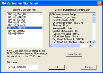
Calibration files may be deleted by selecting the calibration kit in
the Existing Calibration Files
list and then selecting the Delete Cal
File button. This also deletes the corresponding normalization
files on the 86100-based TDR.
Note: Normalization
files are stored on the Keysight 86100 DCA mainframe drive.
Click the OK button to return
to the Select Calibration Kit and Filename
wizard screen.
3. After the calibration kit is selected and the calibration file name
is defined, click the Next >
button to continue with the calibration.
For this example, the selected calibration kit is set to the Default 3.5mm selection and the default
calibration file name.
Define a Calibration Kit
If none of the previously defined calibration kits in the Select the calibration
kit to use: list meets your requirements, you can define your calibration
kit. To define a calibration kit:
Exit the startup wizard by clicking the close button
in the upper right corner of the wizard:  If you
exit the wizard, all previously-defined setup definitions are lost.
From the Utilities
menu, select the TDR System Model (in this case, 86100A|54754A|54754A),
then click Edit Cal Kits
.
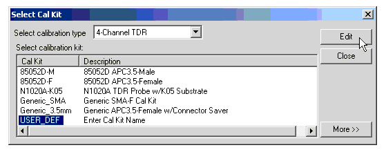
In the Select
Cal Kit dialog box, make sure 4-Channel
TDR is selected in the Select
Calibration Type list, then select the USER_DEF
selection and click Edit
to start the process.
The calibration kit definition is performed in the
Edit TDR Calibration
Kit dialog box. Enter Cal
Kit ID and Name
into the appropriate entry boxes in the header. The Cal Kit ID
is listed in the Cal Kit column
and Name is listed in the
Description column of the
calibration kit selection window.
Also enter Connector
Type. You may optionally specify the minimum (Min. Freq. MHz)
and the maximum (Max. Freq. MHz)
frequencies in megahertz. The PLTS software does not currently
use the frequency range information.
Enter the delay values for the open and short standards
Open Delay and Short Delay
entry boxes. Enter the delay values in picoseconds. The value may
be found in the calibration kit documentation if you are using a standard
from a calibration kit. Typically, if you are using an un-terminated
connector or cable as the open, you may enter "0" (zero)
ps as the value for the open.
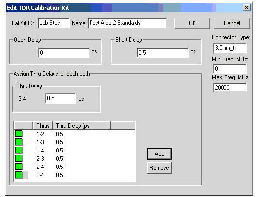
Enter the delay value (in picoseconds) of the thru
in the Thru Delay entry box.
Then, in the list of thrus, select the box at the left of the thru
and click the Add button to
associate the thru to the entered delay value. Repeat this until all
six thru paths are completed.
The color of the box at the left of the thru
changes from red to green as the thru path is completed. Be sure to enter
a delay value for all six thru paths.
If your thru is part of an Keysight (or Hewlett-Packard)
calibration kit, the delay value is listed in the Standard Definitions
section of the calibration kit documentation.
The Remove
button disassociates the delay value with the thru path allowing you to
change the delay value for the path.
All of the thru paths may use the same delay
value or you may have multiple thru delay values if you are using a thru
having a different delay. One instance of using more than one delay value
might be when you are creating a calibration kit definition for probing
and not all of the thru paths would use the same thru delay value.
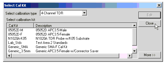
After the Edit
TDR Calibration Kit dialog box is complete, click the OK button to save
the calibration kit with the new information and return to the Select Cal Kit
dialog box shown in displaying the newly defined calibration kit in
the list. Cancel
deletes the information entered and returns to the Select Cal Kit dialog box.
Then click the Close
button to close the dialog box.
Return to the Startup
Wizard by selecting New
from the File
menu to make your measurement. Refer back to Starting the Startup Wizard.
Calibrate TDR and Modules
After selecting the calibration kit, verifying the data file, and selecting
the Next > button, the Calibrate
TDR and Modules wizard window is displayed. This wizard window
is used for the entire calibration.
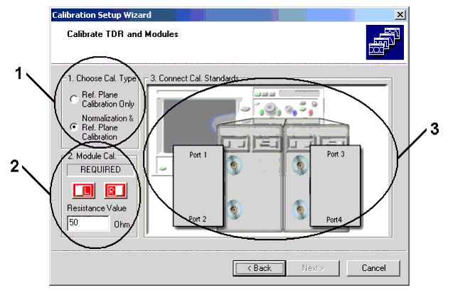
1. Choose Cal. Type
Ref.
Plane Calibration Only:
Available to ALL supported TDR systems.
Adjusts the reference plane at the end of the cables.
Does NOT compensate for loss in the cables.
Automatically de-skews the cables when differential
measurements are selected.
Positions the trace on the display for easy viewing.
Recommends the module calibration.
Normalization
& Ref. Plane Calibration:
Available ONLY with the Keysight 86100-based TDR system
using the 86100's built-in differential TDR/TDT normalization feature.
Has all of the features as the reference plane calibration
selection listed above.
Is the most complete and accurate TDR calibration.
Removes cable loss, mismatch, and reflection errors
which can be significant.
Requires the module calibration.
Note: Beginning with
Keysight 86100-based TDR system firmware 4.2, you can now perform
normalization on common mode stimulus measurements (Tcc, Tdc).
The prompts for calibration standards will differ from previous
versions. You can also adjust rise time after calibration.
|
2. Module Cal (also
called the vertical channel calibration)
Calibrates the module gains, offsets, and timing for
each channel.
Available to all supported TDR systems.
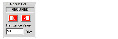
"L" represents the left module (channels 1 and 2)
"R" represents the right module (channels 3 and 4).
A text box indicates the status of the module calibration. The module
calibration is NOT always required. The color of the module calibration
icon also shows the status of the module calibration.
Red - REQUIRED
Yellow - RECOMMENDED
Green - VALID.
Requirements for Module calibration vary between the Tektronix and Keysight
instruments. In general, the Tektronix instruments rarely requires you
to calibrate. The Keysight instruments require module calibration when
any of the following are true:
Performing Normalization
& Ref. Plane Calibration:
The instrument power has been cycled.
The module has been removed and then reinserted.
The ambient temperature changes more than 5C since
the last module calibration
Resistance Value
- Allows you to enter the resistance value of your load. The default value
is 50 ohms.
How to Perform a Module Calibration
Enter the resistance value of your load in the Resistance
Value text box if it varies from the current value.
Click the L
icon to start the module calibration.
Follow the PLTS prompts to perform the module calibration
for the left module. When the module calibration is complete, the
L icon color changes to green.
Repeat steps 2 and 3 to perform the Right module calibration.
The module calibration procedure is now complete and the module calibration
factors are stored in the non-volatile memory in the modules.
CAUTION If
either of the module calibrations fail, you may still be able to complete
the calibration and make a measurement. However, the accuracy of the measurement
will be in doubt. It is recommended that you reattempt the module calibration
before proceeding and correct the equipment problem, if there is one.
3. Connect Standards
This procedure does the following:
Sets the reference plane at the end of the cables.
Automatically de-skews the cables if differential
measurements are selected.
Performs normalization (if Normalization
& Ref. Plane Calibration is selected) which removes cable
loss, mismatch, and reflection errors.
Automatic De-Skewing
Unmatched cables and differences in the path of the
TDR module cause skew in differential and common signals.
Skew must be removed to provide accurate differential
measurements.
De-skewing is required for Reflection and Transmission
measurements.
PLTS removes the reflection skew by measuring the
amount of skew, and then adding 1/2 of the amount to the appropriate
channel. PLTS then repeats the process, iteratively adjusting the
channels until the rest of the skew is removed.
After reflection is de-skewed, thrus are used to connect
Channel 1 to channel 3 while channel 2 is connected to channel 4.
The time difference is measured in the two TDT signal paths and de-skewing
is applied to the appropriate channel correcting the transmission
response.
PLTS can remove skew of up to 780 ps in the Keysight
TDR system and of up to 340 ps in the Tektronix TDR systems.
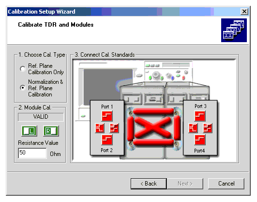
The icons that are displayed depend on the calibration and measurement
parameters that are selected during the initial setup in Select
the Calibration and Measurement Parameters. The following shows
when each of these icons are displayed and which calibrations are required
based on the selected parameters.
For all Icons the color indicates the state of completion:
RED - Cal Needed
BLUE - Cal in Process
GREEN - Cal Complete
Reflection Paths for Single-Ended, Differential-Mode, and Common-Mode
Calibration Parameters
Icon |
Definition |
Selected
Reflection Parameters |

|
Single-Ended |
All
single-ended TDR parameters. |

|
Differential
Mode |
All
TDR parameters having a differential stimulus (TDD11, TCD11, TDD22,
TCD22) |

|
Common Mode |
All TDR parameters having a
common stimulus (TDC11, TCC1, TDC22, TCC22) |
Thru Paths Required by the Parameters Selected
The transmission parameters are calibrated using thru connections at
the ends of the cables. Some of these thru path icons may not be displayed
when you are performing a calibration. As with the reflection icons shown
above, the icons that are displayed depend on the calibration and measurement
parameters that are selected during the initial setup in Select
the Calibration and Measurement Parameters. The following table
also shows when each of these icons are displayed and which calibrations
are required based on the selected parameters.
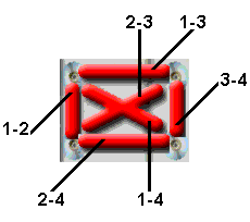
Thru
Paths Icons Displayed on Wizard |
Thru
Paths |
Single-Ended
Parameters |
Differential
Parameters |
|
1-2 |
T12
and T21 |
N/A |
1-3 |
T13
and T31 |
TXX12
or TXX21, where
XX is DD, DC, CD, or CC1 |
1-4 |
T14
and T41 |
N/A |
2-3 |
T23
and T32 |
N/A |
2-4 |
T24
and T42 |
TXX12
or TXX21, where
XX is DD, DC, CD, or CC1 |
3-4 |
T34
and T43 |
N/A |
1 When a differential parameter
warrants the thru path calibration on either thru path 1 - 3 or 2 -
4, the calibration of the other thru path is required and is performed
at the same time.
How to Connect Cal Standards to Perform the Calibration
Click a RED icon in the Connect
Cal Standards area to start the calibration.
You may click the icons in any order.
Follow the PLTS software prompts on your PC rather
than following any prompts that is displayed on your TDR instrument.
TDR icons
represent RELFECTION parameters; TDT
represents TRANSMISSION parameters.
Continue until all icons are GREEN.
You can re-calibrate any parameter if you suspect
there is an error. Select the GREEN icon that represents the suspect
parameter and follow the prompts.
Click Next
> to complete the calibration.
Making a Measurement
The Measurement process includes:
Connect
the DUT This step shows you how to connect your DUT
to the PLTS.
Select
the initial displayed format of the measurement This
step guides you through selecting which of the ten analysis formats
that the upcoming measurement will initially be displayed in. The
measurement can be displayed in any of the 10 formats at any time.
Modify
the measurement stimulus and measured parameters This
optional step allows you to make last minute changes to the measurement
stimulus dialog box and the measurement parameter dialog box. Only
changes that will not require a recalibration may be made.
Run
the measurement This step guides you through starting
the measurement and displaying the data when the measurement is complete.
It also directs you to save the measurement and points you to the
chapters that will assist in your data analysis.
Connect the DUT
1. After saving the calibration data and selecting the Next > button, the Device
connection scheme for TDR calibrations window is displayed. This
wizard window shows how to connect your DUT to the TDR system to make
the measurement. Connect the DUT to the TDR system as shown and then click
the Next >
button.
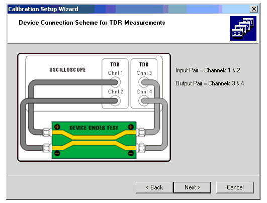
Select the Initial Displayed
Format of the Measurement
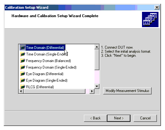
1. The Hardware and Calibration Setup
Wizard Complete window is displayed.
This window is the software location to select the one of ten analysis
formats that the measurement will be displayed as initially. The analysis
formats are:
Time Domain (Differential) Frequency Domain (Balanced) Eye Diagram (Differential) RLCG (Differential) RLCG (W-Element) |
Time Domain (Single-Ended) Frequency Domain (Single-Ended) Eye Diagram (Single-Ended) RLCG (Common) RLCG (Self/Mutual) |
Note: Your PLTS
application may not include the optional RLCG analysis feature.
For the purpose of this example, the Time
Domain (Differential) format icon is selected.
Modify the Measurement Stimulus and
Measured Parameters
1. The Modify Measurement Stimulus
button opens the Measurement Stimulus
dialog box. This dialog box allows you to change some of the measurement
stimulus settings that you set up previously.
Settings that would require a recalibration are not active and may not
be changed in this dialog box. To change the stimulus settings that are
inactive, you must click the <
Back button until you get back to the window described in Set Up the TDR.
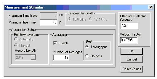
For the purpose of this example, leave the settings unchanged and click
the OK button.
The Reset Values
button resets any active values (any values that can be changed without
requiring a recalibration) to their original default values prior to being
changed in To
Set Up the TDR.
The Cancel button resets any changes
that were made after opening this dialog box.
Note: After the
measurement has been made, you may verify these changes were made by printing
a characterization report. See Characterization
Report Generator for help.
2. Once you exit the Measurement
Stimulus dialog box, the Select
Measurement Parameters dialog box is displayed. The left side of
the dialog box lists all 16 of the TDR single-ended measurements. As with
the dialog box described in Select the Calibration
and Measurement Parameters, the right side of the dialog box
lists all 16 of the TDR differential measurements. Only the parameters
for which the calibration is valid are active. You may select all of the
active parameters or you may select a subset of these parameters. Selecting
a subset of the parameters may save you some measurement time.
Note: Beginning
with PLTS Rev 5.0, when ONLY Balanced parameters are measured, PLTS can
recalculate the Single-Ended S-parameters if enough Balanced data is measured.
To do this, Import the Balanced measurements, then Export the Single-Ended
parameters.
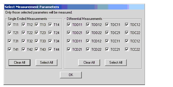
To measure parameters that are inactive, you must click the < Back button until you get back to
the window shown in Select the Calibration
and Measurement Parameters and reselect the parameters. However,
note that if you change the parameters in this window, you may be required
to perform additional portions of the calibration.
For the purpose of this example, leave the parameters unchanged and
click the OK button.
3. With the Hardware and Calibration
Setup Wizard Complete window is displayed, select the Next >
button to start the measurement.
Run the Measurement
1. The software displays the wizard's Measurement
& Post-Processing Status window and starts the measurement
and the measurement post-processing. The software makes each of the measurements.
The status of the measurements and the post-processing is displayed in
the status text area. The status may also be observed by watching the
status bar at the right edge of the text area. As the measurements and
the post-processing proceed, the color of the bar gradually changes to
blue.
Once the post-processing is complete, click the Next
> button to display the measurement results in the main PLTS
window.
Analyzing the Measurement Results
Now that the measurement has been made, the main Physical Layer Test
System (PLTS) window gives you the flexibility to perform analysis on
the measured data in a variety of ways. Learn
more.
CAUTION To
ensure the measurement data is not lost, save the measurement data by
clicking File, then Save.


