![]()
![]()
All digital interconnect components or channels require an interface to the Coax connections of the PLTS. These interfaces - called fixtures or probes - typically introduce loss and discontinuities that mask the true performance of your component or channel. You must be aware of fixture and probing effects and account for them in your measurement setup.
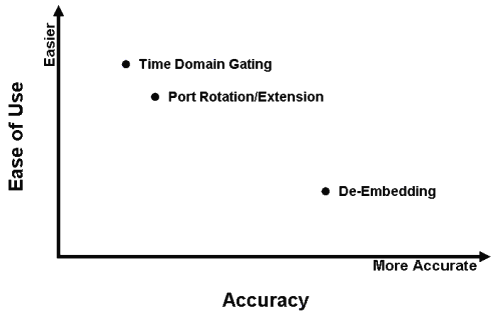
There are multiple approaches to removing fixture and probing effects. Calibration to the reference plane is one way to remove effects. Another is to use post-processing techniques such as Gating, Port Rotation/Extension and De-Embedding. All of these techniques are applied to fully corrected (calibrated) measurement data. They do not directly effect the calibration. However, you can combine good calibration techniques with one or more of these post-processing fixture removal techniques to obtain the best measurement accuracy.
Caution: If you have not yet saved your measured data, save it before removing any of these unwanted effects by selecting Save from the File menu.

Gating provides the ability to remove the effect of a particular circuit element mathematically from time-domain plots. The gated section removes a section of the plot that you define, replacing it with an ideal transmission line having the same electrical delay as the removed section. By observing the original frequency domain response and the transformed frequency domain response, the effect of the gating operation on the S-parameter data can be seen.
Port Rotation/Extension (part of the Reference Plane Adjustment) mathematically extends the measurement plane to the DUT, but assumes the fixture looks like a perfect transmission line: a flat magnitude response, a linear phase response, and a constant impedance. Port rotation/extension is done after a coaxial calibration has been performed at the end of the test cables. If the fixture is very well designed, this technique may be sufficient.
De-embedding (part of the Reference Plane Adjustment) affords a very accurate technique that removes the effect of added loss, phase shift, and mismatch due to adding adapters, probes, and fixtures to your DUT. It combines the errors determined from a coaxial calibration with the errors in the fixture to obtain a single error coefficient array that corrects for everything up to the measurement plane of the DUT. De-embedding uses an accurate linear model of the fixture, or measured S-parameter data of the fixture. This modeled or measured data is then mathematically removed from the DUT measurement data in post-processing.
|
Note If you have a 7xP N-port License, you can use the following Reference Plane Adjustment features:
|