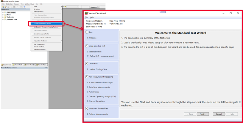
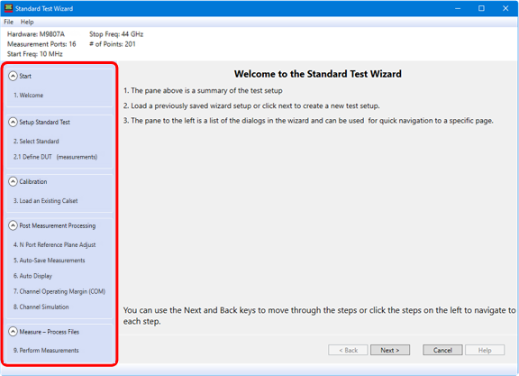
The Standard Test Wizard is used to set up tests, embedding/de-embedding, calibration, and measurement results. These set ups can be saved for later use.
Note: The Standard Test Wizard is not compatible with DCA and E5071 instruments.
In this topic:
|
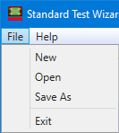
The File pull-down menu is used to save a test that was set up using the Standard Test Wizard, open an existing setup, create a new setup, or exit the wizard. Selecting New will clear the Standard Test Wizard of all settings.
|
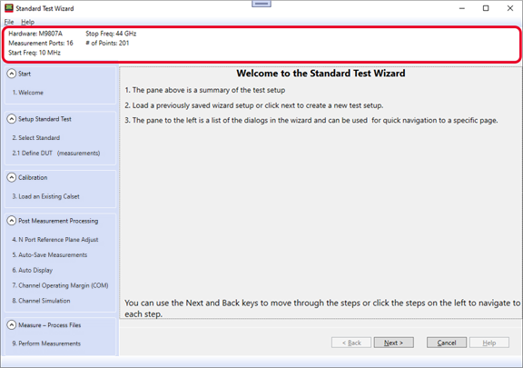
The test setup summary is displayed in the top part of the Standard Test Wizard dialog as shown below.
The test setup summary information is defined in the Welcome to PLTS dialog, which is part of the Startup Wizard. Test setups can be saved/loaded from this dialog. Learn more.
|
The Next/Back buttons can be used to move through the selections shown in the navigation pane.
|
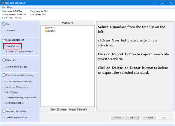
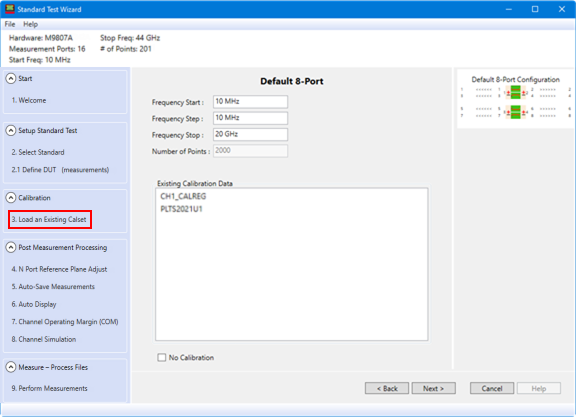
The Select Standard dialog is used to set up the DUT configuration.
Expand the folders in the Standard pane to select an existing standard. The following example shows the settings with the Default 8-Port standard selected.
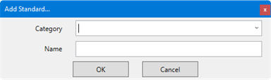
Frequency Start - Sets the start frequency of the sweep. Frequency Step - Sets the step size between points. This value is normally locked to (is the same as) the Frequency Start value. Frequency Stop - Sets the stop frequency of the sweep. Number of Points - Sets the number of measured points per sweep. Note: PLTS requires at least 11 data points. This limitation also exists when loading Cal Sets. New button - Creates a new standard under one of the existing categories (click on the down arrow) or creates a new standard under a new category.
Delete button - Deletes the selected standard. Import button - Imports a previously saved standard. Export button - Exports the selected standard.
|
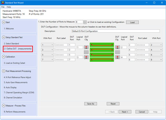
The Define DUT dialog allows the selected standard for the DUT to be edited.
1. Enter the number of DUT ports to calibrate and measure - Beginning with PLTS 2018, the maximum number of DUT ports is 64. Or click Load to recall a previously saved configuration (*.dcf) file. Description - File name of the current configuration. Change this text, then click Save As to store the current configuration to a *.dcf file using this file name. VNA Port - Change the VNA port number. The E5071C ENA has some limitations that must be considered. See E5071C Limitations. Port Label - For the PNA/ Single-ended DUT port. The text replaces input and output arrows (<<<< and >>>>). DUT Port
Logical Port - For differential pairs, the logical port is comprised of two DUT ports. For single-ended ports, the logical port can be a different number than the DUT port. DUT Cfg
Save As button - Store the current configuration. This file can later be recalled using the Load button. Reset button - Recall the Default Configuration. Cancel button - Discards the changes you made since open the dialog and closes the dialog.
|
Select a calset that is currently stored in the VNA from the Existing Calibration Data list.
No Calibration check box - Check to not use calibration data.
|
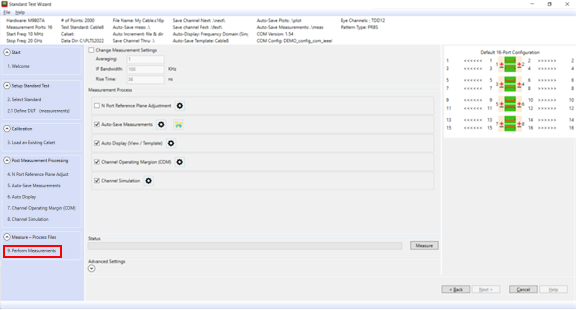
The Perform Measurements dialog is used to set up post measurement processing.
Change Measurement Settings - Check to allow setting changes. Averaging - Sets the number of averages. Each data point of consecutively swept traces is mathematically averaged until the total number of sweeps is equal to the averaging factor. This effectively lowers the noise floor, but also slows the measurement time. IF Bandwidth - Sets the IF bandwidth. Narrower (smaller) IF bandwidths lower the noise floor so that low-level signals can be viewed, but slows the measurement time. Rise Time - Sets the transition time (in ns) of the stimulus signal rising from 10 to 90% of the maximum signal amplitude.
Measurement Process N Port Reference Plane Adjustment
- Check to use the N Port Reference Plane Adjustment to remove
unwanted effects introduced by adapters, fixtures, etc. To change
the settings, click on the corresponding settings icon ( Auto-Save Measurements
- Check to automatically save measurement settings. To change
the settings, click on the corresponding settings icon ( Auto Display (View / Template)
- Check to automatically display the template, save the template
image, save plots, and save measurement results. To change the
settings, click on the corresponding settings icon ( Channel Operating Margin (COM)
- Check to perform a channel operating margin test. To change
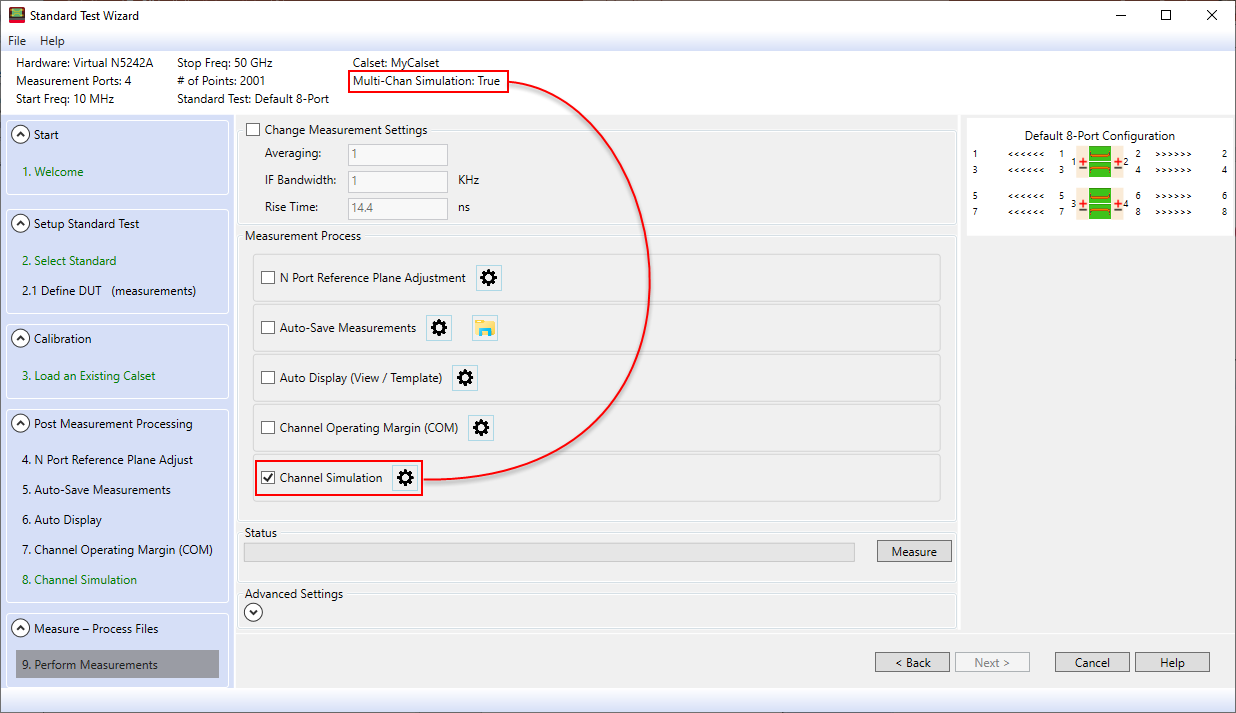
the settings, click on the corresponding settings icon ( Channel Simulation -
Check to enable channel simulation. To change the settings, click
on the corresponding settings icon ( Measure button - Start the measurement process. Status - Displays the measurement progress and displays status at the bottom of the dialog during the measurement.
(measNumber) - Measurement number set automatically or can be manually entered.
|
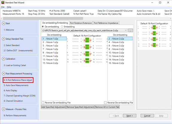
The N Port Reference Plane Adjustment to remove unwanted effects from the measurement.
De-embedding/Embedding Tab De-embedding - Mathematically removes the effects of characterized device, such as an adapter or fixture, from the measurement. Embedding - Mathematically adds the effects of the characterized device to the measurement. SnP file name - Selects/Loads a SnP file to embed or de-embed. Click on the "..." button to load a file from a local directory or click on the down arrow to select a previously loaded file. Reverse De-embedding File - Check to reverse, or 'mirror' the device port numbers as they are applied to the DUT port. Add Specified Adjustment button - Adds the currently selected SnP file to the currently selected DUT port in the De-embedding columns. Remove Specified Adjustment button - Removes the SnP file from the currently selected DUT port in the De-embedding columns. Remove All in Current Tab button - Removes all SnP file selections from all DUT ports in the De-embedding columns.
Port Rotation/Extension Tab Specify Rotation - Enter the rotation in millimeters (mm). The equivalent time in picoseconds (ps) is also displayed.
Add Specified Adjustment button - Adds the current rotation adjustment to the currently selected DUT port in the Rotation columns. Remove Specified Adjustment button - Removes the rotation adjustment from the currently selected DUT port in the Rotation columns. Remove All in Current Tab button - Removes all rotation adjustments from all DUT ports in the Rotation columns..
Port Reference Impedance Tab Single-Ended - Selects single-ended impedance. Diff/Comm - Selects differential and common mode impedances, which are de-coupled and can be changed independent of the single-ended impedance. Learn more. Specify the impedance in ohms - Enter real numbers between 0.0 ohms and 1000.0 ohms by 0.1 ohm increments using the Up/Down arrows. You can enter values to 11 places to the right of the decimal using the keyboard. Add Specified Adjustment button - Adds the current impedance adjustment to the currently selected DUT port in the Impedance columns. Remove Specified Adjustment button - Removes the impedance adjustment from the currently selected DUT port in the Impedance columns. Remove All in Current Tab button - Removes all impedance adjustments from all DUT ports in the Impedance columns..
|
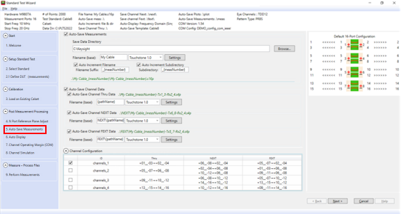
The Auto-Save Measurement dialog automatically saves measurement information such as the directory to use for data, file naming convention, and channel data.
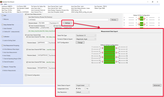
Auto-Save Measurements Save Data Directory (Process File Directory) - Type a full path or click Browse, then navigate to a folder. Filename (base) - Type the base filename. Settings button - Accesses the Measurement Data Export dialog to export the configuration:
Select File Type - Use the drop-down menu to select the file type. Format of Data to Export - Use the drop-down menu to select from the following formats based on the file type:
DUT Configuration/Change - Click on the Change button to access the DUT Configuration dialog. Refer to DUT Configuration for information about these settings. Select Data to Export - Select data to export based on the data format. Independent Units - Select units based on the data format. Max Resolution - Sets the maximum resolution from 0 (default) to 15. Auto Increment Filename - Check to increment the filenames automatically using the filename suffix to create unique file names. Filename Suffix - The suffix is automatically appended to the filename. When saving more than one file, filenames are automatically generated and saved to the specified folder. The measurement number (measNumber) is used as the filename suffix and increments with each file. File Type - Use the drop-down menu to select the file type. Auto Increment Subdirectory - Check to increment the subdirectories automatically using the subdirectory suffix to create unique subdirectories. Subdirectory - The suffix is automatically appended to the subdirectory. When saving files to more than one subdirectory, the subdirectory names are automatically generated. The measurement number (measNumber) is used as the subdirectory suffix and increments with each subdirectory.
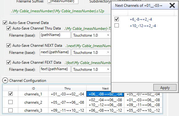
Auto-Save Channel Data Auto-Save Channel Thru Data - Check to save the channel thru data. Filename (base) - Type a directory path. If the path is not changed, then the path and base filename defined under Auto-Save Measurements is used as the directory to store results. Settings button - Accesses the Channel Thru Export dialog. The functions are the same as the export dialog for Auto-Save Measurements. Auto-Save Channel NEXT Data - Check to save the channel NEXT data. Filename (base) - Type a directory path. If the path is not changed, then the path and base filename defined in Auto-Save Measurements and a \next subdirectory is created where results will be stored. Settings button - Accesses the Channel Next Export dialog. The functions are the same as the export dialog for Auto-Save Measurements. Auto-Save Channel FEXT Data - Check to save the channel FEXT data. Filename (base) - Type a directory path. If the path is not changed, then the path and base filename defined in Auto-Save Measurements and a \fext subdirectory is created where results will be stored. Settings button - Accesses the Channel Fext Export dialog. The functions are the same as the export dialog for Auto-Save Measurements.
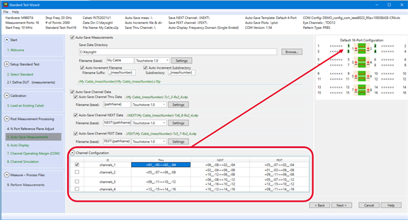
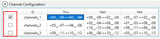
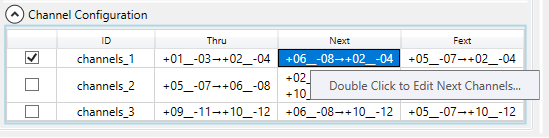
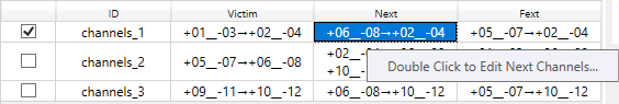
Channel Configuration The Channel Configuration is accessed by clicking on the down arrow to display the channel thru/next/fext port configuration by channel:
Select the channel(s) of interest by checking the left-most column.
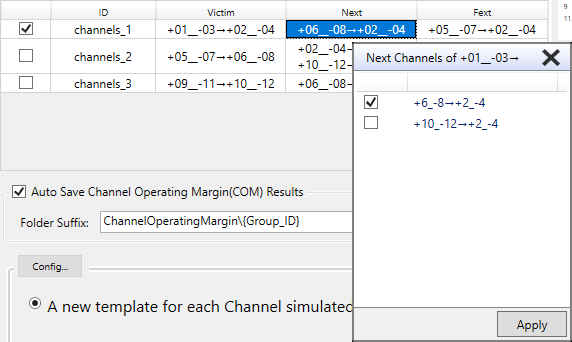
Double-click in the Next or Fext columns to edit the channels.
Select the Next or Fext channel(s) by checking the corresponding box.
|
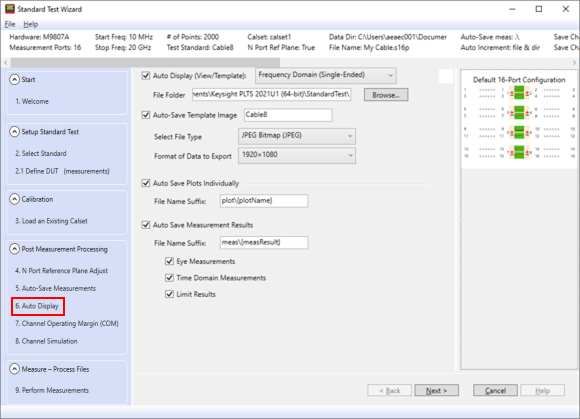
The Auto Display dialog sets up the template view, template image, plots, and measurement results.
Auto Display (View/Template) - Check to display the template view. Select Domain - Use the drop-down menu to select a domain. File Folder - Select a folder to store the template, template image, plots, and/or results. Auto-Save Template Image - Check to save an image of the template. Select File Type - Use the drop-down menu to select an image file type. Format of Data to Export - Use the drop-down menu to select the image resolution. Auto Save Plots Individually - Check to create a separate file for each plot. File Name Suffix - Type a name for the file suffix for each plot name. Auto Save Measurement Results - Check to save measurement results. File Name Suffix - Type a name for the file suffix for each measurement. Eye Measurements - Check to include eye measurements. Time Domain Measurements - Check to include time domain measurements. Limit Results - Check to include limit results.
|
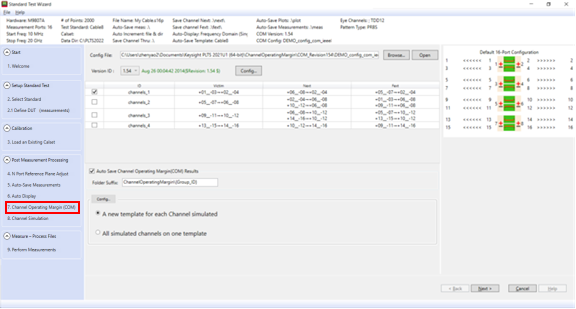
The COM dialog is used to set up a channel operating margin test.
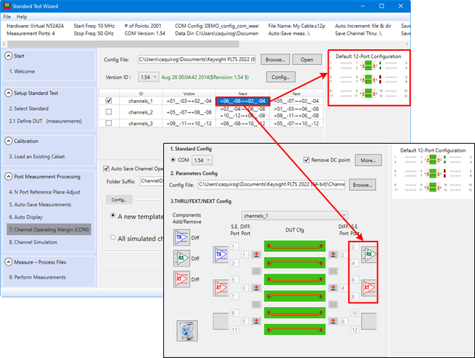
Config File - Click the Browse... button to specify the path to the config file. Learn more. Open button - Click to open the currently loaded config file. Version ID - Select between COM version 1.54, 1.65, and version 2.28. Config... button - Accesses the Channel Operating Margin dialog. The following is an example showing the Next configuration selected for channel_1. Upon selection, the diagram in the upper-right changes to reflect this configuration. When the Config... button is clicked, the Next configuration is displayed in the Channel Operating Margin dialog.
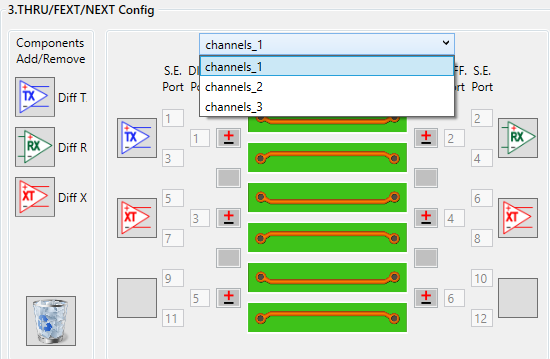
Once in the Channel Operating Margin dialog, the configurations for the other channels can be displayed by selecting the channel:
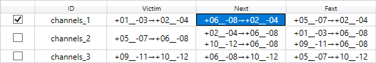
For descriptions of the other settings in this dialog, refer to the Channel Operating Margin topic. Channel Configuration Select the channel(s) of interest by checking the left-most column.
Double-click in the Next or Fext columns to edit the channels.
Select the Next or Fext channel(s) by checking the corresponding box.
Auto Save Channel Operating Margin (COM) Results - Check to save the COM results automatically. Folder Suffix - Type a name for the folder suffix for the COM results. The {Group_ID} uses the ID name shown in the channel configuration table. For example, channels_1. Config... button - Configures the COM output to PLTS trace data. A new template for each Channel simulated - Select to generate a new template for each simulated channel and display the template name under Template View in the Data Browser. All simulated channels on one template - Select to generate a new template containing all simulated channels and display the template name under Template View in the Data Browser.
|
|
To enable multi-channel simulation, mark the Channel Simulation checkbox. Then click the gear icon to configure the simulation, as needed.
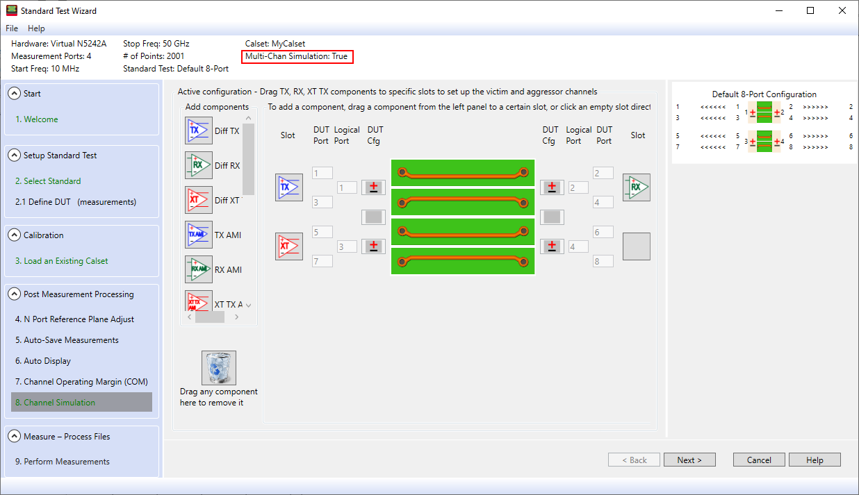
Multi-Channel Simulation configuration screen.
|


 ) or select