Configure DC Sources and DC Meters


Once configured, one or more DC Sources and DC Meters can be controlled by the PNA. DC Power Analyzers are also supported, but they must be configured as a separate Source and Meter.

The Keysight N6700 series and B2900 series DC Analyzers are supported with configuration files that can be loaded on the DC Meter and DC Source property page. Once loaded, the SCPI commands that control the DC device can be modified and saved. Learn how.

See Also

External DC Meter Data Conversion


How to Configure a DC Meter or DC Source

  1. Important: Create a DC Source / Meter device by name (one-time). Learn how (separate topic).

  2. On the Configure an External Device dialog, click Device Properties. (This topic).

Using front-panel
hardkey
[softkey] buttons

Using Menus

  1. Press system

  2. then [Configure]

  3. then [External Device Configuration]

  1. Click Utility

  2. then System

  3. then Configure

  4. then External Device Configuration


Once configured, set the DC source voltage and display DC meter measurements:

  • DC Sources:  DC Source control is available in Standard, Gain Compression/GCX , and FCA channels.  

    • Set the Start and Stop voltage on the DC Control dialog. To access this dialog:  Press Sweep, then More, then DC Source.

  • DC Meters:  DC meter measurements are available in Standard, Gain Compression /GCX, Swept IMD / IMDX, and FCA channels.

    • In Gain Compression /GCX, Swept IMD / IMDX, and FCA channels, display DC parameters as you would an RF parameter, by clicking Trace/Chan, then New Trace.

    • In a Standard channel, configure an unratioed measurement. Press Meas, then More, then Receivers. For Numerator, select the external (or internal) DC meter.

    • Change the X-axis to display the DC Meter parameters, click Response, then Display, then Labels, then Select X-Axis, then select the DC Meter.


DC Source / Meter Configuration dialog box help

The DC Source and DC Meter properties are almost identical in how they operate. Both are documented here.

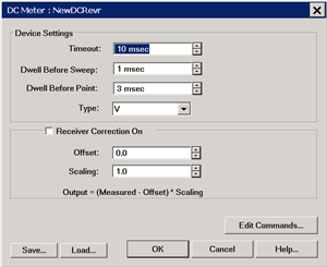
Device Settings

Timeout - Sets a time limit for the DC source or meter to make contact with the PNA. If this time limit is exceeded, the PNA stops the measurement and displays the following error message.

EXECUTION ERROR;OPC QUERY TIMEOUT ERROR

If this occurs, check the connections between your PNA and external device.

Dwell Before Sweep  Wait time before making a sweep.

Dwell After Point

  • DC source  Wait time after setting the voltage/current at each data point.

  • DC meter  Wait time before measuring voltage/current at each data point.

Type: This setting changes the units that are displayed in the DC Source dialog, the X-axis display annotation, and the underlying data format. Use these settings with Receiver or Source Correction (Scaling and Offset) to display and scale measurements with these units. Choose from:

V (volts - default)

dBm

F (degrees)

A (amperes)

W (watts)

C (degrees)


K (kelvin)

Note: To change the X-axis to display the DC Meter units, click Response, then Display, then Labels, then Select X-Axis, then select the DC Meter.

Receiver / Source Correction

  • For a DC source, use the correction settings to scale and offset the output voltage.

  • For a DC Meter (receiver), use the correction settings, along with Type, to display and scale measurements with appropriate units.  For example:

Measure the voltage across a 5 ohm resistor, then display the results in A(mperes).

Using ohms law,  I = V / 5 ohms or I = V *.2

For receiver correction, enter Scaling = .2; Offset = 0.


ON  Check to apply the following correction factors to each measurement.

Offset: Enter the value to offset the DC Meter reading or set the DC Source voltage.

Scaling: Enter the value to scale the DC Meter reading or set the DC Source voltage.

Displayed Output = (Measured / Set value - Offset) * Scaling value.

Edit Commands - Click to start the Edit Commands dialog.

Important Note:

The Edit Commands dialogs (see below) MUST be completed. They are used to set the SCPI commands with which the PNA communicates with the DC device.

These commands are saved, along with other configuration settings, to configuration (*.xml) files. These files can then be loaded later when communicating with the same DC Device.

Configuration files for the Keysight N67xx and B29xx Power Analyzers are pre-loaded on the PNA. Click Load, then navigate to: c:\users\public\network analyzer\documents\drivers.


Save - Press to save the current DC Source or DC Meter configuration to an *.xml file. The list of files is NOT filtered by "DCMeter" or "DCSource", so use a descriptive filename.

Load - Press to load an existing configuration.


DC Meter Edit Commands dialog box help

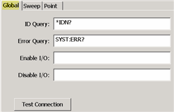
Global Tab

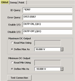
The Global tab includes the system settings for the DC Meter.

ID Query - Enter the SCPI command to return the ID string of the DC Meter. Typically *IDN?

Error Query - Enter the SCPI command that is used to return DC Meter errors. Typically SYST:ERR?

Enable I/O - Enter the SCPI commands that is used to enable the DC Meter to read voltages.

Disable I/O - Enter the SCPI commands that is used to disable the DC Meter from reading voltages.

Test Connection

Click to start the Test Connection dialog. You must first have entered the I/O Configuration settings  and select Enable IO on the External Device dialog.

Enter a SCPI command, then click Send or Send&Read when a return value is expected.

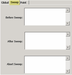
Sweep Tab

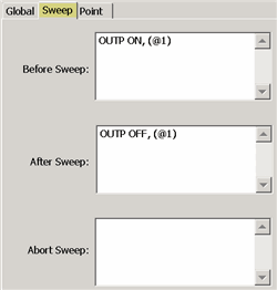
Use the Sweep Tab to send SCPI commands to the DC Meter at the beginning or end of each sweep.

Abort Sweep - Enter the SCPI command that is used to Abort or reset the DC Meter. This would be necessary when the PNA sweep is aborted or terminated. The PNA will then send the command to the DC Meter.

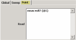
Point Tab

Read (commands) - Enter the SCPI command that is used to make a DC measurement at each data point.

Set (commands) - Use <%variable> to make a DC Meter setting.


DC Source Edit Commands dialog box help

Global Tab

The Global tab includes the system settings for the DC Source.

ID Query - Enter the SCPI command to return the ID string of the DC Source. Typically *IDN? This entry can be left blank.

Error Query - Enter the SCPI command that is used to return DC Source errors. Typically SYST:ERR?

Enable I/O - Enter the SCPI commands that is used to enable the DC Source to output voltages.

Disable I/O - Enter the SCPI commands that is used to disable the DC Source from outputting voltages.

Maximum / Minimum DC Output

Read Max / Min Using - Select, then enter the commands used to return the output limits of the DC source.

Define Max / Min As - If the DC Source has no commands to return these values, or you would rather define the limit for your DC Source, select then enter the Max and Min voltage limits.

Test Connection

Click to start the Test Connection dialog. You must first have entered the I/O Configuration settings  and select Enable IO on the External Device dialog.

Enter a SCPI command, then click Send or Send&Read when a return value is expected.

Sweep Tab

Use the Sweep Tab to send SCPI commands to the DC Source at the beginning or end of each sweep.

Typically, you might send the output ON at the beginning of each sweep, and output OFF at the end of each sweep as shown above.

Abort Sweep - Enter the SCPI command that is used to Abort or reset the DC Source. This would be necessary when the PNA sweep is aborted or terminated. The PNA will then send the command to the DC Source.

Point Tab

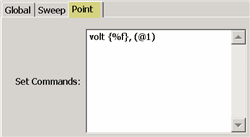
Note: The DC Source output voltages are configured on the DC Source dialog.

This dialog is used to configure the commands that are used to communicate with the DC Source.

Set commands - Enter the SCPI command, enclosed in {curly brackets} to output (set) a voltage/current from the DC Source for each data point.

  • {%f} - The value is a double value. (Most common).

  • {%d} - The value is a integer. This would be used when the voltage controls a remote switch. For example, you can program the value to: “0,1,0,1,0,1….”. where “0”  = OFF and “1” = ON.