Saving IMDx Data (Swept IMD topic)
Conceptually, Swept IMD for Converters (IMDx) is like IMD for Amplifiers, except that there are two sets of products on the DUT output.

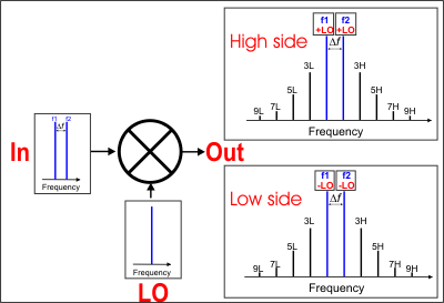
This image shows the simplest measurement configuration: the Input, LO, and Output are all CW frequencies.
DUT INPUT - two fundamental tones (f1 and f2)
DUT LO - a single frequency.
DUT OUTPUT - two sets of frequencies
With IMDx, you can view EITHER the High side or Low side products; NOT BOTH.
Make this selection on the Mixer Frequency tab.
|
|
High side (Input PLUS LO and all ordered products) |
|
Low side (Input MINUS LO and all ordered products) |
Swept IMDx requires Swept IMD (Opt 087) and FCA (either Opt 082 or 083).
When using Integrated Pulse application, the IF Filter setting for the relevant receiver must be changed to 'Wide'. Learn how. The default IF Filter setting in Swept IMD is 'Narrow' in order to avoid spurs and harmonics. The IF Attenuator setting (on the same dialog) may also require adjusting.
The following PNA features are NOT available with Swept IMDx:
Analog Sweep (Stepped sweep mode only)
Log frequency sweeps
Unratioed receiver measurements (A, B, R)
Save Formatted Citifile data.
External Test Set Control (Option 551)
Independent IFBW, Power Levels, or Sweep Time in a segment table is NOT supported.
External DC Sources (DC Meters ARE supported).
Note: Beginning with A.09.00, Embedded LO measurements are allowed in IMDx and IMSpectrum. Configure the measurement as you would with SMC. Learn how.
The PNA is extremely versatile, and can be configured in many ways to make IMDx measurements. While not all conceivable configurations are documented here, a few of the most common examples are provided to show the basic concepts.
The DUT Input must be connected to PNA Port 1 which supplies the f1 and f2 tones.
The DUT Output must be connected to PNA Port 2 which uses the PNA B receiver.
See LO Source configuration below.
Three sources are required to make IMDx measurements: Two sources are PNA internal; the third is an external source.
F1 tone - Must come out PNA Port 1 Default is Src 1
F2 tone - Must come out PNA Port 1 through the internal combiner. This source can come from an internal or external source. Default is the internal Src 2.
LO - Can come from internal or external source. Default is Not controlled, set to 0 Hz.
If using the internal Src 2 source, the f2 tone must come from an external source through the rear-panel.
If using an external source, it can be connected directly to the DUT, or through the PNA Port 3 or Port 4 using the Path Configurator.
Three configurations are shown below to illustrate how to use the Path Configurator to manually make switch settings.
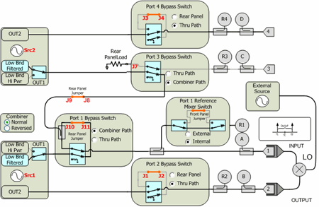
IMDx and IMx Spectrum channels are ALWAYS configured using the default configuration switch settings shown in the image below. This is NOT the same default configuration that is used for an S-parameter channel. A manual switch setting is required whenever a custom configuration is used.
The manual switch setting, which must be done every time an IMDx or IMx Spectrum channel is created, can be saved using the Store button in the Path Configurator. Then save the entire IMDx setup as an Instrument State. This will load the custom Path Configuration when the Instrument State is recalled.

1. Default Configuration No manual switching required.
f1 - Internal Src1
f2 - Internal Src2 through combiner in Normal
LO - Connect external source directly to the DUT LO.
2. External LO though Port 3 or Port 4 (4-port PNA only)
Use this configuration to monitor LO power using R3 or R4. (Future parameters)
f1 - Internal Src1
f2 - Internal Src2 through combiner in Normal
LO - Connect external source through the rear-panel ( J7 for Port 3; J3 for Port 4 ).
Connect the DUT LO to PNA Port 3 or Port 4.
For Port 3, NO switching is required.
For Port 4, switch Port 4 Bypass Switch to Rear Panel.
3. Internal LO through Port 3 or Port 4; External f2 through rear-panel (4-port PNA only)
This configuration is commonly used for FCA measurements where the internal second source is used as the LO.
f1 - Internal Src1
f2 - External f2 through rear-panel J9. No switching required.
LO - Internal Src2 through:
Port 3 Switch Port 3 Bypass Switch to Thru Path.. Connect the DUT LO to PNA Port 3
Port 4 Switch Port 4 Bypass Switch to Thru Path. Connect the DUT LO to PNA Port 4
On the PNA front panel, press Meas then [Measurement Class]
Select Swept IMD Converters, then either:
OK delete the existing measurement, or
New Channel to create the measurement in a new channel.
A Swept IMDx measurement is displayed. To select additional parameters to display, click Response, then Measure, then select a parameter from the list.
How to start the Swept IMDx Setup dialogTo provide quicker access, use the Setup softkey. Learn how. |
|
|
Using front-panel |
Using Menus |
|
|
TipsAlthough you will soon become comfortable navigating these tabs, at first it may be best to complete the dialog in the following order:
|
The following are the Valid Mixer Configurations in table format:
|
Sweep Type |
Input |
LO |
Output |
|
Swept Input (Fixed Tones) |
|||
|
Sweep fc |
Swept |
Swept |
Fixed |
|
Swept |
Fixed |
Swept |
|
|
All Ranges Fixed |
|||
|
CW Sweep Delta F (Tone) Power Sweep LO Power Sweep |
Fixed |
Fixed |
Fixed |
|
Fixed Input / Swept LO & Output |
|||
|
CW |
Fixed |
Swept |
Swept |
For determining a valid mixer configuration with 2 LOs, one Fixed LO and one Swept is equivalent to having a single-stage Swept LO.
If you create an invalid Sweep Type / Mixer Configuration, a red message appears like the following:
![]()
If this occurs, change the Sweep Type on the Tone Frequency tab.
The following is an explanation of the table:
SWEPT Input - Sweeps the center frequency of the tones, but the tone spacing remains fixed.
On the Tone Frequency tab, select Sweep fc
Either the LO or Output MUST also be swept.
On the Mixer Frequency tab, select Start/Stop, or Center/Span for each range to be swept.
FIXED Input - The center frequency of the tones is fixed.
On the Tone Frequency tab select Fixed for the following sweep type:
CW - Tones do NOT change. The LO and Output frequencies CAN be swept.
All Ranges FIXED - The center frequency of the tones is fixed.
On the Tone Frequency tab select Fixed for the following sweep types:
Sweep Delta F Tone separation changes.
Power Sweep - Tone power changes.
LO Power Sweep - The LO power is swept.
CW - Tones do NOT change.
The following tabs are shared with the Swept IMD Setup dialog:
The following tabs are shared with all Mixer / Converter Applications
Mixer Setup tab (NOT shared)
|
|
|
|
|
|
|
Converter Stages Choose from 1 or 2 stage DUT (# of LOs). Converter ModelLearn how to configure an external source and combiner to make Swept IMD and IMDx measurements. f1 Always uses PNA internal source 1. (DUT Input) Port N (Red circle in image) Normally Port 1 is used. This selection is available to allow the two tones to be routed through port 3 on 4-port PNA models. Learn more. f2 Select a source to be used for the f2 tone. This selection is available when an external source is configured and the Active box is checked on the External Source Configuration dialog. LO1 (and LO2 for 2-stage DUTs) Select the source to use for the specified LO. Available for selection when an external source is configured and the Active box is checked on the External Source Configuration dialog. (DUT Output) Port N Available for selection on 4-port PNA models. Select the PNA port to connect to the DUT Output. Fractional Multipliers - Learn more.
Hardware ConfigurationAdd Source Click to configure an external source using the External Source Configuration dialog. Path Configuration Click to launch the Path Configuration dialog (PNA-X models only). |
|
|
How to add Swept IMDx Parameters |
|
|
Using front-panel |
Using Menus |
|
|
|
This dialog is shared with Swept IMD for Amplifiers. |
Calibration for IMDx is exactly the same as calibration for IMD with the following exception:
You can choose to perform a source power cal of the LO source. If the LO is a fixed frequency, this step is performed very fast.
The results of an IMDx calibration are very similar to the results that are achieved from an SMC calibration.