Simulated Source Settings
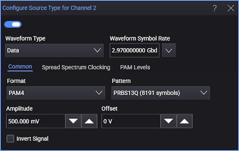
Use the Configure Source Type dialog box to configure the fundamental settings of your simulated source waveform.
To invert the waveform, select Invert Signal.
Once your waveform is defined, select  to turn on the waveform.
To view the waveform on the oscilloscope, click the channel button in the Configure Simulation Source dialog box.
Always perform an Auto Scale after configuring the source waveform.
Source Waveform Type
Use the Waveform Type field to select a Data, Clock, Function, DC, or Load from File.
For Data waveforms, use the Format field to select the type of simulated data format: NRZ,PAM3, PAM4, or PAM6. Select the Pattern from one that is shown in the following table.
| Selection | Format | Description | |||
|---|---|---|---|---|---|
| NRZ | PAM3 | PAM4 | PAM6 | ||
| One - Zero | ♦ | Pattern of repeating 101010… | |||
| PRTS 7 (2186 symbols) | ♦ | 37−1 pseudo-random symbol sequence (2186 symbols). | |||
| PRBS 7 (127 symbols) | ♦ | ♦ | 27−1 pseudo-random symbol sequence (127 symbols). | ||
| PRBS 7 (128 symbols) | ♦ | ♦ | 27 pseudo-random symbol sequence (128 symbols). | ||
| PRBS 9 (511 symbols) | ♦ | ♦ | 29−1 pseudo-random symbol sequence (511 symbols). | ||
| PRBS 9 (512 symbols) | ♦ | ♦ | 29 pseudo-random symbol sequence (512 symbols). | ||
| PRBS 11 (2047 symbols) | ♦ | ♦ | 211−1 pseudo-random symbol sequence (2,047 symbols). | ||
| PRBS 11 (2048 symbols) | ♦ | ♦ | 211 pseudo-random symbol sequence (2,048 symbols). | ||
| PRBS 13 (8191 symbols) | ♦ | ♦ | 213−1 pseudo-random symbol sequence (8,191 symbols). | ||
| PRBS 13 (8192 symbols) | ♦ | ♦ | 213 pseudo-random symbol sequence (8,192 symbols). | ||
| PRBS 15 (32767 symbols) | ♦ | ♦ | 215−1 pseudo-random symbol sequence (32,767 symbols). | ||
| PRBS 15 (32768 symbols) | ♦ | ♦ | 215 pseudo-random symbol sequence (32,768 symbols). | ||
| Linearity (160 symbols) | ♦ | ♦ | A PAM4 linearity (160 symbols). | ||
| Linearity (224 symbols) | ♦ | A PAM6 linearity (224 symbols). | |||
| JP01A (2 symbols) | ♦ | A signal with repeated sequence of two symbols that transition from level 0 to level 1. | |||
| JP01B (62 symbols) | ♦ | A signal with 15 pairs of symbols that transition from level 0 to level 1 followed by 16 pairs of symbols that transition from level 1 to level 0 for a total of 62 symbols. | |||
| JP01C (62 symbols) | ♦ | A signal with seven sets of the four symbols 0011 followed by three 0 symbols and then seven sets of the four symbols 1100 followed by three 1 symbols for a total of 62 symbols. | |||
| JP02A (2 symbols) | ♦ | A signal with repeated sequence of two symbols that transition from level 0 to level 2. | |||
| JP02B (62 symbols) | ♦ | A signal with 15 pairs of symbols that transition from level 0 to level 2 followed by 16 pairs of symbols that transition from level 2 to level 0 for a total of 62 symbols. | |||
| JP02C (62 symbols) | ♦ | A signal with seven sets of the four symbols 0022 followed by three 0 symbols and then seven sets of the four symbols 2200 followed by three 2 symbols for a total of 62 symbols. | |||
| JP03A (2 symbols) | ♦ | A signal with repeated sequence of two symbols that transition from level 0 to level 3. | |||
| JP03B (62 symbols) | ♦ | A signal with 15 pairs of symbols that transition from level 0 to level 3 followed by 16 pairs of symbols that transition from level 3 to level 0 for a total of 62 symbols. | |||
| JP03C (62 symbols) | ♦ | A signal with seven sets of the four symbols 0033 followed by three 0 symbols and then seven sets of the four symbols 3300 followed by three 3 symbols for a total of 62 symbols. | |||
| JP05A (2 symbols) | ♦ | A signal with repeated sequence of two symbols that transition from level 0 to level 5. | |||
| JP05B (62 symbols) | ♦ | A signal with 15 pairs of symbols that transition from level 0 to level 5 followed by 16 pairs of symbols that transition from level 5 to level 0 for a total of 62 symbols. | |||
| JP05C (62 symbols) | ♦ | A signal with seven sets of the four symbols 0055 followed by three 0 symbols and then seven sets of the four symbols 5500 followed by three 5 symbols for a total of 62 symbols. | |||
| K28.5 (20 symbols) | ♦ | ||||
| PRBS9Q (511 symbols) | ♦ | PRBS9Q (511 symbols). | |||
| PRBS13Q (8191 symbols) | ♦ | PRBS13Q (8,191 symbols). | |||
| PCIe (8768 symbols) | ♦ | PCIe (8,768 symbols). | |||
| SSPR (32762 symbols) | ♦ | SSPR (32,762 symbols). | |||
| SSPRQ (65535 symbols) | ♦ | SSPRQ (65,535 symbols). | |||
| Pseudo Random (2 to 65,536 symbols) | ♦ | ♦ | ♦ | ♦ | A pseudo-random symbol pattern whose length is specified by the Pattern Length field (2 to 65,536 symbols) and whose initial value is indirectly specified by the Seed field. |
For Function waveforms, you can select from the functions:
- Sine
- Cosine
- Square
- Pulse — With this selection, there is an additional field for specifying the pulse width attribute.
- Triangle
- Sawtooth
If you select Load from File, you can click Browse to select a waveform file. Both .h5 and .csv formats are supported. This feature allows you to work offline with your data. It is recommended that you also save a Infiniium setup file when you save your original waveform. When you load the waveform file, also load the setup file to ensure that the Infiniium settings match those of your waveform file.
Waveform Symbol Rate
Use the Waveform Data Rate field to enter the waveform's symbol rate or click Select From List to choose a standard symbol rate.
Waveform Amplitude and Offset
Use the Amplitude and Offset fields to enter the simulated waveform's amplitude and offset in volts for electrical waveforms and Watts for optical waveforms. You can change only the Offset of a DC waveform.
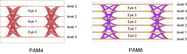
PAM4/PAM6 Level Adjustment
To create a waveform that has non-linearity, use the PAM Levels subtab:
- PAM4 — Use the Level 1 and Level 2 fields. By default, level 1 is set to 33.3% and level 2 is set to 66.7%.
- PAM6 — Use the Level 1, Level 2, Level 3, and Level 4 fields. By default, level 1 is set to 20%, level 2 is set to 40%, level 3 is set to 60%, and level 4 is set to 80%.
You can perform a Linearity measurement on the PAM waveform and eye diagram.
The ability to adjust the amplitude of PAM levels requires the Pulse Amplitude Modulation PAM-N Analysis Software.
Spread Spectrum Clocking
Available with the Clock and Data waveform types, the Spread Spectrum Clocking option lets you modulate the symbol rate of a simulated signal.
Spread Spectrum Clocking (SSC) is used to reduce the peak electromagnetic radiation at the nominal clock frequency. With SSC, the clock pulse is modulated with a relatively low-frequency waveform that has a specified pattern/shape. SSC broadens a clock or data signal spectrum and reduces its peak energy.
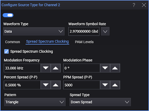
Modulation Frequency — Specifies the frequency of the modulating signal, in other words, how often the modulation cycle (from initial symbol rate to the spread frequency and back) completes.
Modulation Phase — Specifies the phase of the modulating signal. This control shifts when the modulating signal pattern begins and ends. If the acquisition time is less than the period of the modulating signal, you can use this control to specify which portion of the modulating pattern is applied.
Percent Spread (P-P) or PPM Spread (P-P) — Specifies the magnitude of the symbol rate change (spread) as a percent or its parts-per-million (PPM) equivalent. These two fields give you different ways of specifying the same value. With percent, the entered number is divided by 100. With PPM, the entered number is divided by 1,000,000.
Pattern — Specifies the shape of the modulating signal which determines the rate of change in the output symbol rate. For example, a constant rate of change from the symbol rate to the lower frequency (when using Down Spread) followed by a constant rate of change from the lower frequency back to the symbol rate is a Triangle pattern/shape. You can select: Sinusoidal, Triangle, Square, or Sawtooth.
Spread Type — Specifies how the symbol rate is spread to different frequencies and back. You can select:
- Center Spread — The waveform symbol rate is modulated to lower and higher frequencies about the specified symbol rate. The signal's average data rate stays the same.
- Up Spread — The waveform symbol rate is modulated to a higher frequency and back. The signal's average data rate increases by half of the spread amount.
- Down Spread — The waveform symbol rate is modulated to a lower frequency and back. The signal's average data rate decreases by half of the spread amount.