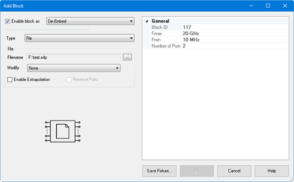
This function specifies a SnP file to embed (add) or de-embed
(remove) from the measurement results. Computation takes place
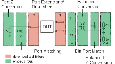
BEFORE Balanced conversion.
The SnP file S-Parameter data is normalized
to a single File-Zo impedance as defined in the file.
The VNA will re-normalize the S-Parameter data from File-Zo
to the VNA System-Zo.
The VNA will interpolate if the number of data points that are
read is different from the current VNA setting.
Note:
De-embedding a component with more than 20 dB of loss becomes
impractical because of an inability to accurately measure the
match of the DUT through such a device.
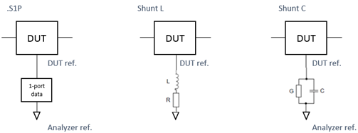
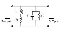
The de-embedding operation recalls an .s2p file (Touchstone
format) which includes the electrical characteristics of a 2-port
fixture or device. The file can be in any standard format (real-imaginary,
magnitude-angle, dB-angle).
Enable block as Check
to apply the settings to the measurement results. Must also enable
Fixturing
ON/off.
De-Embed/Embed Select
the embed (adding the snp device virtually) or de-embedding (removing
the snp device).
Note:
Port Matching circuits can only be "embed".
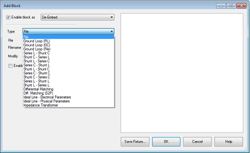
File
Name: Select the snp file for embeding or de-embeding
Modify:
If the block has high loss, then
it may cause transmission measurement errors when full S-parameter
correction is applied. The reason is that the DUT output match
cannot be measured accurately through a high-loss path; if the
fixture has a large mismatch then this error will cause errors
in the transmission measurement. Zeroing the fixture reflection
at the DUT will reduce this error. This problem is described in
"Handbook of Microwave Component Measurements with Advanced
VNA Techniques", Joel Dunsmore, John Wiley & Sons, page
592 in the First Edition and page 775 in the Second Edition.
None:
does not modify the block. Set
Snn=0 @ DUT - will set all reflection parameters on
the DUT-side to zero.
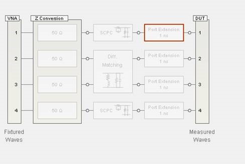
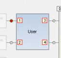
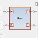
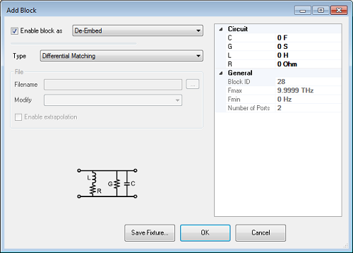
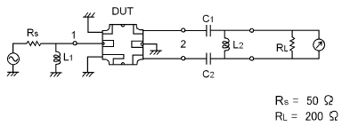
For the 4-terminal
fixture shown above, it will set S33=s44=0. This is useful for
fixtures that have low crosstalk between DUT-side ports. Set
Snn=XTalk=0 @ DUT - will set all reflection and crosstalk
parameters on the DUT-side to zero.
This selection is not
available for a 2-terminal fixture. For the 4-terminal
fixture shown above, it will set S33=S44=S43=S34=0. This is useful for
multiport fixtures which have a lot of crosstalk between
the DUT-side ports.
Enable Extrapolation Check to apply a simple extrapolation
when the SnP file has a narrower frequency range than the channel.
The values for the first and last data points are extended in
either direction to cover the frequency range of the measurement.
The frequency ranges of the SnP file are displayed at the
right of the dialog.
When extrapolation is necessary
and enabled, a message is displayed showing the frequency range
to be extrapolated. When extrapolation is necessary and disabled,
a message is displayed offering to enable extrapolation.
Note: For
DIQ application channels, the SnP file must cover all specified
frequency ranges, unless extrapolation is selected.
Note: For IMD and
IMDX channels, you will be prompted for extrapolation as described
above if the S2P file does not meet the port frequency conditions. However, if
the file is valid, extrapolation will be enabled automatically. This is for
compatibility reasons with the IMD/IMDX calsets, which list all
frequencies for all ports. This applies only for the SnP
section, NOT the ground loop section. Ground loop is not for IMD/IMDX.
General
(Right side of Dialog box)
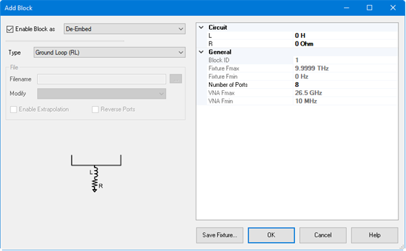
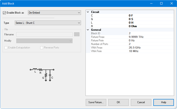
Block ID
Block ID. This is the same number as the circuit number
in SCPI.
Fmax
show the maximum frequency of imported snp file
Fmin
show the minimum frequency of imported snp file.
Number
of Port show the number of port of imported snp file
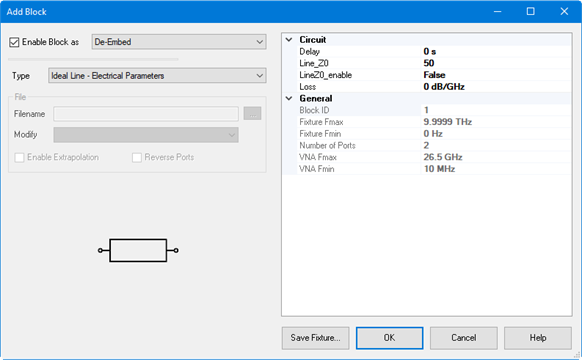
Reverse
Ports Reverses the ports on an existing S2P file.
Save Fixture... Save
the SnP file of the specified circuit. When the block is defined
as "Embed", the outputted SnP files is the inversed
S-paramemter. When you need normal SnP, put this circuit only
in the Fixture Generator dialog box and
output SnP file by File
> Save Topology As SnP. |