How to access Interface Control settings
Using Hardkey/SoftTab/Softkey
Using a mouse
Press Setup > Internal Hardware > Interface Control...
Click Instrument
- Select Setup
Select Internal Hardware
Select Interface Control...
![]()
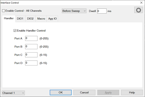
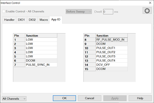
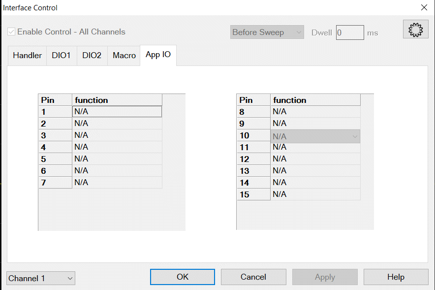
The Interface Control feature allows you to send remote commands and data to the following SSA rear-panel Interfaces: GPIB, Material Handler I/O, and Auxiliary I/O.
Other System Configuration Topics
The Interface Control feature allows you to send data to control external equipment such as GPIB instruments, a material handler or other equipment, without needing to create a remote program. The SSA-X manages the timing and required interface setup. See Rear Panel Tour.
A unique set of control data can be sent for each channel. In addition, a unique set of control data can be sent before the channel sweep starts, and after the sweep ends.
Interface Control settings can be copied to other channels using Copy Channels.
Control data can only be WRITTEN to the interfaces, NOT READ from the interfaces.
Handler IO Tab |
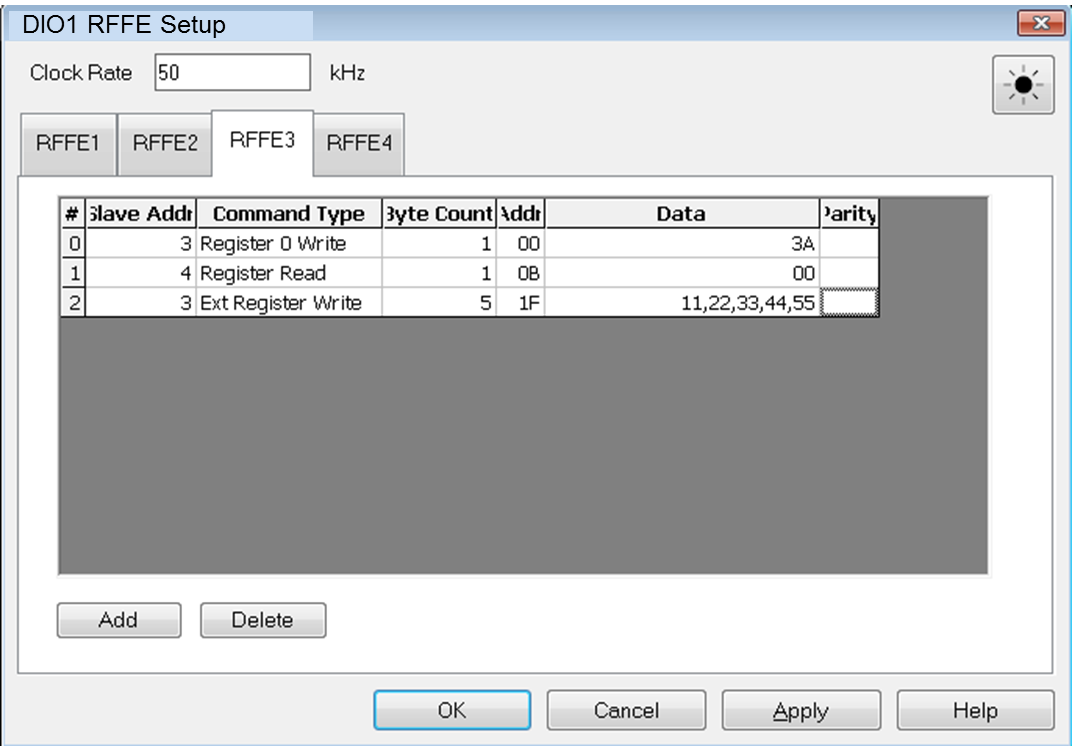
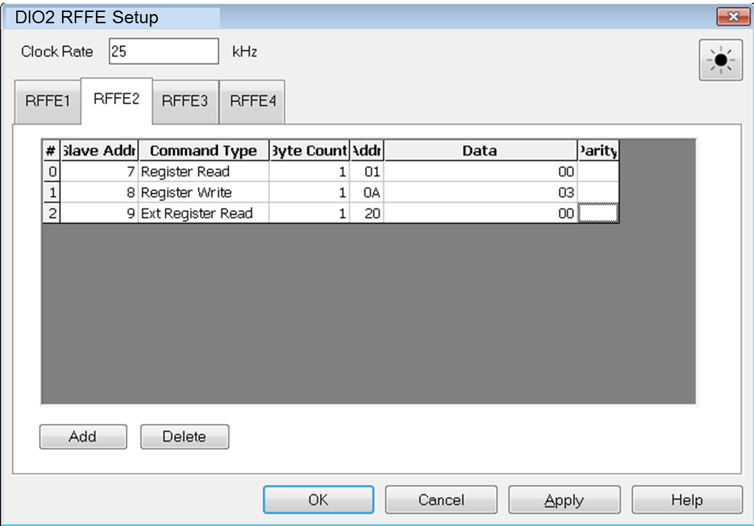
Clock Rate Specify the clock rate from 25 kHz to 25 MHz. Possible values are 50000/n, with integer n, 2000 to 2. RFFE 1-4 Tabs # RFFE command sequence number up to 16 Slave Addr Specify the slave address in decimal. The slave address should be from 0 to 15 (4 bits). Command Type Select the RFFE command sequence type.
Byte Count Specify byte count value in decimal. The value range is depending on command sequence type setting.
Addr Specify the address value in hex Integer value. The value range is coupled with command sequence type setting.
Data Specify or read the data in hex value. Comma separated of data values. The value length is coupled with byte count setting. Parity The Parity field is valid if Byte Count is Register Read or Extended Register Read. Show the parity bit value for each data byte. Add Adds one line of RFFE command to the table. Delete Deletes one line of RFFE command from the table. OK Applies the settings of the DUT control related parameters and closes the DIO RFFE Setup dialog and back to Interface Control dialog . Cancel Does not apply changes that were made, and closes the DIO RFFE Setup dialog and back to Interface Control dialog.. Apply Will apply all settings from within the dialog. Help Display help topic of the dialog. |