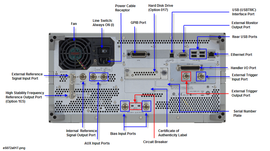
The Aux Input Ports are used to input DC signal for DC signal measurement.
This BNC female connector allows external bias to be applied at the test ports.
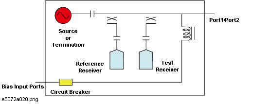
Do not apply DC voltage exceeding 35 Volt.
When the Circuit Breaker is activated, bias cannot be applied to the bias input ports.
The label shows the license information of the Windows Operating System
The circuit breaker is used to break the input current from the Bias Input Ports. When currents exceeding 1 Ampere is applied to the bias input ports, the circuit breaker is activated. From the rear panel, it is observed that the white bars of the circuit breaker are ejected slightly. To reset the circuit breaker, push the white bars back to its original position.
A terminal for conanecting the E5072A to a LAN (Local Area Network). Connecting this instrument to a LAN enables you to access the hard disk drive of this instrument from an external PC or to control this instrument by using SICL-LAN or telnet.
|
Specification |
Value |
|
Connector type |
8-pin RJ-45 connector |
|
Base standard |
10Base-T/100Base-TX/1000Base-T |
A terminal to which an external color monitor (display device) can be connected. By connecting a color monitor to this terminal, the same information shown on the LCD screen of the main body can be displayed on an external color monitor.
Connector type: 15-pin VGA connector, female
The reference signal input connector for phase-locking the measurement signal from the E5072A to the external frequency reference signal. Inputting the reference signal to this connector improves the accuracy and frequency stability of the measurement signal from the E5072A.
|
Specification |
Value |
|
Connector type |
BNC connector, female |
|
Input signal (Typical) |
10 MHz ± 10 ppm, -3 dBm to +10 dBm |
When the frequency reference signal is input to this connector, the measurement signal from the E5072A is automatically phase-locked to the reference signal. When an input signal is not present, the frequency reference signal inside the E5072A is automatically used. The ExtRef on the instrument status bar is displayed in blue when the system is phase-locked to the external reference signal and in gray when not phase-locked.
When using Option 1E5 (high stability frequency reference), connect this connector to the High Stability Frequency Reference Output Connector (Ref Oven, Option 1E5 only) by using the BNC(m)-BNC(m) cable included with the option.
A connector to which external trigger signals are input. This connector detects the downward transition from the HIGH state in TTL signals as the trigger signal. To use this connector to generate a trigger, you must set the trigger source to the "external" side (key operation: Trigger > Trigger Source > External).
Connector type: BNC connector, female
The External Trigger Output Port can output the pulse with the specified polarity either before or after the measurement of each point.
The External Trigger Output Port can safely handle a maximum Output Current of 50mA.
|
Symbol |
Parameter |
Typical Value |
Unit |
Condition |
|
|
Pulse Width |
1 |
µsec |
|
|
VOH |
HIGH Level Output Voltage |
5 |
Volt |
Iout=-50µA |
|
VOL |
LOW Level Output Voltage |
0 |
Volt |
Iout=50µA |
The cooling fan for controlling the temperature inside the E5072A. This fan exhausts heated air from inside the analyzer to the outside.
The connection of an external controller through General Purpose Interface Bus (GPIB) connector allows you to configure an automatic measurement system.
This GPIB port is used only for controlling the E5072A from an external controller. Use USB/GPIB interface to control other devices from the E5072A. You cannot control other devices from the E5072A through this GPIB connector.
The terminal to which an automatic machine (handler) used on a production line is connected. See Handler I/O Port.
Connector type: 36-pin Ribbon (Centronics) connector
The E5072A comes with a removable hard disk drive, option 017. For standard options (Option 019), the hard disk drive is not removable.
When Option 1E5 (high stability frequency reference) is installed, the reference signal is output from this connector.
|
Specification |
Value |
|
Connector type |
BNC connector, female |
|
Output signal (Typical) |
10 MHz ± 1 ppm, 0 dBm minimum |
When Option 1E5 (high stability frequency reference) is installed, connect this connector to the External Reference Signal Input Connector (Ref In) by using the BNC(m)-BNC(m) cable included with the option.
A connector for outputting the internal frequency reference signal from the E5072A. By connecting this output connector to the external reference signal input connector of another device, the device can be phase-locked to the internal reference signal of the E5072A and used under this condition.
|
Specification |
Value |
|
Connector type |
BNC connector, female |
|
Output signal (Typical) |
10 MHz ± 5 ppm, 0 dBm ± 3 dBm |
|
Output impedance (Typical) |
50 ohm |
Always keep this switch on (|).
Do not use this switch to turn off (O) the mains. Doing so may cause the analyzer to fail. For more information, see the description of the Standby Switch.
The receptacle (outlet) to which the power cable is connected.
To connect the device to a power source (outlet), use the supplied three-prong power cable with a ground conductor. The plug attached to the power cable (on the power outlet side or device side of the cable) serves as the disconnecting device (device that cuts off power supply) of the E5072A. When the power supply must be cut off to avoid such danger as electric shock, pull out the power cable plug (on the power outlet side or device side of the cable). For the procedure for turning off the mains in normal use, see the description in Standby Switch.
For more on the power supply, see the Installation Guide.
The label showing the product number, serial number and the installed option number. The accessary and system rack options are not listed on this label. (CFGxxx or ATOxxx in the first line is for Keysight Use Only.)
Through this port, you can control the E5072A from external controllers. For more information on the measurement system using the USB port, see the USB Remote Control System.
|
Specification |
Value |
|
Connector type |
Universal serial bus (USB) jack, type B (4 contact positions), Female |
|
Compliance Standards |
USBTMC-USB488 and USB2.0 |
Four USB (Universal Serial Bus) ports are provided that can be used for connecting to ECal (Electronic Calibration) module, USB, Multiport test set or a printer. Connecting a designated ECal module to this port enables ECal measurements to be obtained. Connecting a compatible printer to this port enables screen information on the E5072A to be printed. See Using USB for more details.