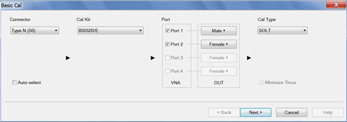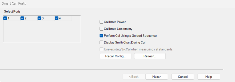
Allows you to select ports to calibrate.
Select Ports All ports are selected by default. User can select which port to calibrate.
Select All (6 ports and more) All ports will be selected
Clear All (6 ports and more) Uncheck all the selected ports.
Calibrate Power Disabled by default. Learn more.
Calibrate Uncertainty (Available PNA only) include measurement uncertainties from calibration.
Perform Cal Using Guided Sequence Check to perform a Guided Power Calibration. Learn more.
Display Smith Chart During Cal When enabled, reflection measurements will be displayed on Smith Chart during calibration.
Use existing SrcCal when measuring cal standards When enabled, and the following conditions are met, the user's existing source power calibration array will be used when acquiring calibration standard data:
-
The user is performing a vector calibration only (no power).
-
A valid source cal is present in the channel being calibrated.
-
The user has elected to enable this feature (via GUI or SCPI).
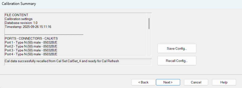
Recall Config... Opens a standard file-browser window for selecting a previously saved calibration configuration data file (*.cfd).
Refresh... Allows user to re-measure the cal standards and then recompute the calibration. After selecting Refresh..., Smart Cal will move to the Calibration Summary page so the user may view the state of the cal that is being refreshed.
This button is grayed out if there is no currently active Cal Set or Cal Register.
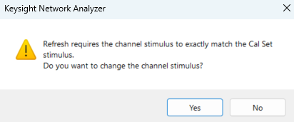
If the user selects Refresh... and the stimulus of the currently active channel does not exactly match the Cal Set stimulus, then a warning dialog will be displayed which allows the user to automatically change the channel stimulus.
If a power cal is going to be performed on a source which has the RF Pulse Modulator enabled, a warning dialog will be displayed when click on Recall Config... , Refresh... or Next>.
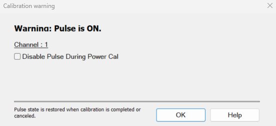
Disbale Pulse During Power Cal Select the checkbox to disable the RF Pulse Modulator on the source being calibrated during the power cal only and will be re-enabled after the power cal.
For Noise Figure calibration using a noise source, the Disable Pulse During Power Cal warning can be ignored.
If the channel is NFX with a controlled LO signal that is being modulated, and the LO is being power calibrated, the pulse warning should be considered.