Source and Receiver Power Calibration can be performed during a standard S-parameter Guided Calibration. This power cal provides the following enhancements over the standard source and receiver power calibration:
A source and receiver power cal can be performed for all PNA ports with a single power sensor connection.
Multiple power sensors can be used to cover wide frequency ranges.
The receivers are corrected automatically.
Optionally compensates for an adapter that may be used to connect the power sensor.
Source and Receiver power correction is stored to the Cal Set along with S-parameter correction.
Note: A Guided Power Calibration is not accurate when Frequency Offset Mode is enabled.
Learn more about the standard Source and Receiver Power Cals.
In this topic:
How to perform a Guided Power Cal
|
On the following Select Ports dialog, check Calibrate source and receiver power, then click Next.
Two Cal Wizard pages later, complete the following dialog.
|
Note: A Use Power Table checkbox (not shown) is available when a mmWave SMC measurement is active. Learn more.
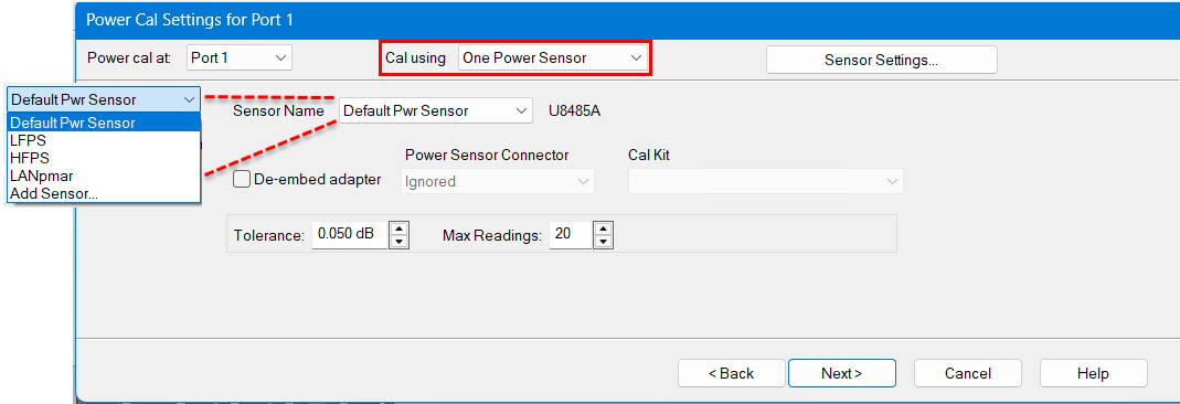
Power Cal at: Select the source port for which a Power Calibration will be performed. The source and receiver correction will be transferred to all other sources and receivers involved in the S-parameter measurements.
Cal using Select the cal method from the list below: One Power Sensor Default choice, use the standard power meter. Multiple Sensors Select this to use one or more power sensors that are configured as PMAR devices. This dialog is replaced with the Multiple Sensors dialog.
Sensor Settings Opens the Configure Power Sensor dialog.
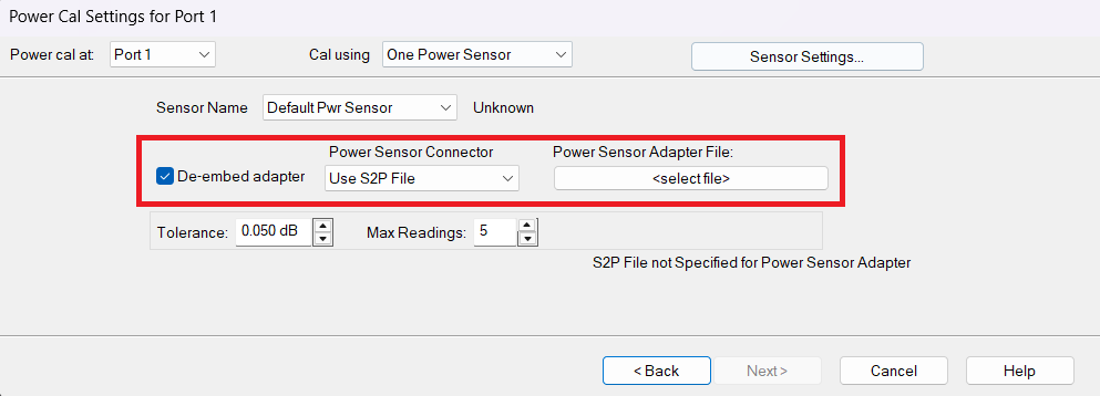
Sensor Name Select or add a power sensor. All power sensors are displayed in the list even if "Active - Show in UI" has been disabled in the External Device Configuration dialog. "Add Sensor..." opens the External Device Configuration dialog to the power meters page where you can configure more sensors. De-embed (power sensor) adapter When the power sensor connector is NOT the same type and gender as the DUT connector for the specified port, then for optimum accuracy, extra cal steps are required to measure and correct for the adapter that is used to connect the power sensor to the reference plane. If the adapter has already been characterized and saved to an S2P file, then this S2P file can be used to compensate fo the adapter without having to add extra cal steps. Clear this checkbox to NOT compensate for the added adapter. Check this checkbox to perform extra calibration steps to measure and correct for the adapter OR if you want to account for the adapter using an S2P file. Then select the Power Sensor Connector type and gender of the power sensor. "Ignored" does NOT compensate for the added adapter, just as if the checkbox were cleared. Select "Use S2p File" to use an S2P file to account for the adapter. When this connector matches the DUT connector for the same port, then the VNA assumes that there is no adapter. Extra cal steps are NOT required and the Cal Kit selection is not available. Otherwise, select the Cal Kit to be used to calibrate at the adapter. You can select "Use S2P File" instead of doing a power sensor adapter cal. Then select the S2P file which represents the S-parameters of the power sensor adapter under Power Sensor Adapter File. This can be applied on Multiple Power Sensor and Single Power Sensor (Default Power Sensor).
Tolerance This value used for sensor settling. When two successive measurements differ by less than the tolerance value, then the sensor is considered to be settled, and the last measurement is used. Tolerance has a special case where a tolerance of 0 will always just return an averaged reading that is simply the mean of Max Readings.
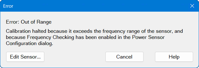
Max Readings Maximum number of readings allowed for sensor settling. Default is 10. See Accuracy Settings below. Import Power Cal Select this to import the power calibration error terms from an existing calset that contains power calibration. Importing the power calibration allows to skip the measurement of the power meter. This dialog is replaced with the Import Power Cal dialog. Source PMax Table Primarily used to calibrate the source of the millimeter head when no sensor is available. This table is referred to as a Source Pmax Table. It defines the head output power across frequency for a given RF input power. This dialog is replaced with the Source PMax Table dialog. Frequency Checking Error Dialog:If frequency checking has been enabled, then the VNA will check that the power sensors are defined over the calibration frequency range. If not, then this error dialog (see below) is displayed when you click the Measure button or, in the case of a Guided Power Calibration, the Next button.
Edit Sensor... Opens the "Configure Power Sensor" dialog for the selected sensor. The sensor I/O is connected automatically so the dialog displays all the settings and controls, rather than just showing the "Sensor Settings..." button. From this page, you can change the sensor settings. Clicking OK returns you directly to the Source Power Cal dialog. Cancel Closes this dialog and returns you to the Source Power Cal dialog. |
|
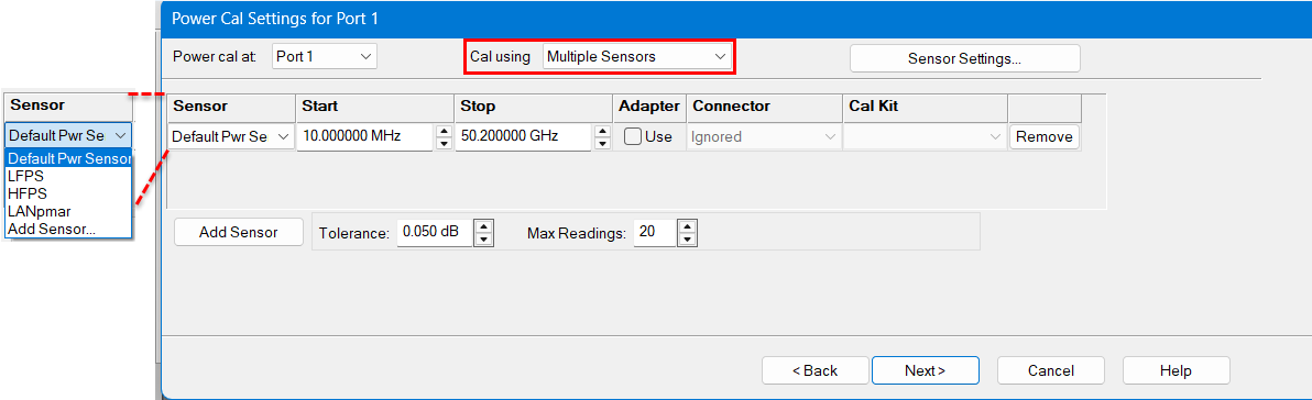
Power Cal at: Select the source port for which a Power Calibration will be performed. The source and receiver correction will be transferred to all other sources and receivers involved in the S-parameter measurements.
Cal using Select the cal method from the list below: One Power Sensor Default choice, use the standard power meter. Multiple Sensors Select this to use one or more power sensors that are configured as PMAR devices. This dialog is replaced with the Multiple Sensors dialog.
Sensor Settings Opens the Configure Power Sensor dialog. Sensor GridSensor Select the power sensor and the associated Start and Stop frequency range. Adapter When the power sensor connector is NOT the same type and gender as the DUT connector for the specified port, then for optimum accuracy, extra cal steps are required to measure and correct for the adapter that is used to connect the power sensor to the reference plane. Clear this box to NOT compensate for the added adapter. Check this box to perform extra calibration steps to measure and correct for the adapter. OR if you want to account for the adapter using an S2P file. Then specify the Power Sensor Connector type and gender of the power sensor. When this connector matches the DUT connector for the same port, then extra cal steps are NOT required, and the Cal Kit selection is not available. OR, you can select "Use S2P File" to use an S2P file to account for the adapter. Otherwise, select the Cal Kit to be used to calibrate at the adapter. If "Use S2P File" is selected, then the Cal Kit selection changes to a button that can be used to select the File. User can select "Use S2P File" instead of doing a power sensor adapter cal. Select the S2P file which represents the S-parameters of the power sensor adapter under Cal Kit. Remove Click to remove the power sensor from the list. Add Sensor Click to add a new line, then click the down-arrow to select a sensor. If a power sensor does NOT appear in the list, click the Sensor Settings button to configure a power sensor. Frequency Checking Error Dialog:If frequency checking has been enabled, then the VNA will check that the power sensors are defined over the calibration frequency range. If not, then this error dialog (see below) is displayed when you click the Measure button or, in the case of a Guided Power Calibration, the Next button.
Edit Sensor... Opens the "Configure Power Sensor" dialog for the selected sensor. The sensor I/O is connected automatically so the dialog displays all the settings and controls, rather than just showing the "Sensor Settings..." button. From this page, you can change the sensor settings. Clicking OK returns you directly to the Source Power Cal dialog. Cancel Closes this dialog and returns you to the Source Power Cal dialog. Accuracy
Tolerance This value used for sensor settling. When two successive measurements differ by less than the tolerance value, then the sensor is considered to be settled, and the last measurement is used. Tolerance has a special case where a tolerance of 0 will always just return an averaged reading that is simply the mean of Max Readings.
Max Readings Maximum number of readings allowed for sensor settling. Default is 10.
The readings that were taken are averaged together to become the "settled" reading. Set Power For Best Accuracy Select to use the power level associated with the best uncertainty for a specific power meter. |
|
| Programming Commands |
|
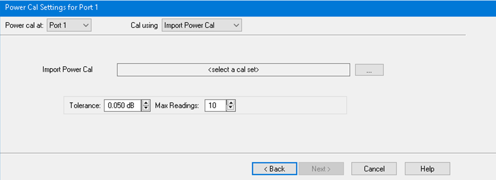
Import Power Cal Use the "..." button to open the calset selection dialog, and import the calset containing the power calibration. The imported calset must contain a Full + power calibration at the port specified by the "Power cal at" pulldown list. The imported calset can contain different ports than the ones currently being calibrated. If the stimulus frequencies are different, interpolation is performed by default. Extrapolation is not allowed. See Accuracy Settings above.
|
| Programming Commands |
|
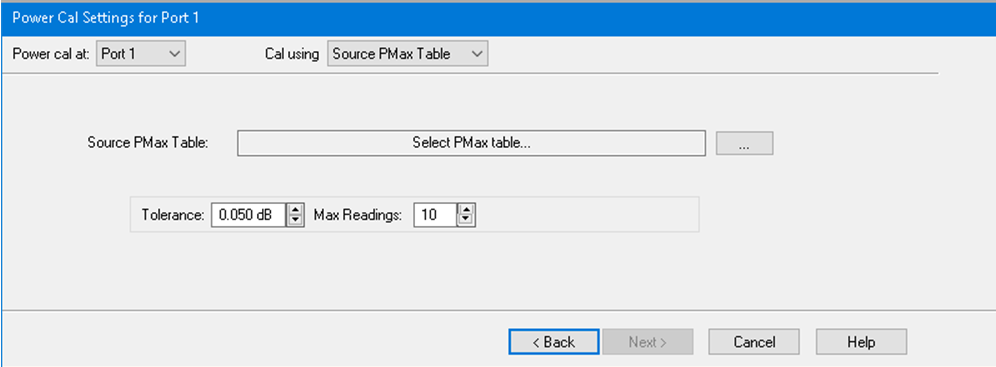
Select PMax Table Use the "..." button to open the PRN file that stores the power table. File content requirements:
See Accuracy Settings above.. |
| Programming Commands |
|
Power Level Set the power level at which the Source Power Cal is to be performed. It is usually best to perform the Source Power Cal at 0 dBm because the power sensor is calibrated at that level. If 0 dBm is not achievable for your measurement, then set to the power level with the lowest level of measurement noise. |
Accessing Correction Methods |
|
|
Using Hardkey/SoftTab/Softkey |
Using a mouse |
|
|
During a Guided Power Cal, the match between the power sensor and the VNA source port is measured. The source power correction array is compensated to account for the measured mismatch. In addition, the reference receiver measurement is also compensated to account for the mismatch of the DUT.
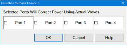
How to turn OFF match correction:
Click Cal > Main > Correction Methods.... then click on the Exclude all ports button.
|
The following dialog applies to the Spectrum Analyzer applications only.
The following dialog applies to the Modulation Distortion, Modulation Distortion Converters and Intermodulation Distortion applications only. Note: Actual Wave and 8-term error correction method in IMD/IMDX is a Licensed Feature. Learn more about Licensed Features.
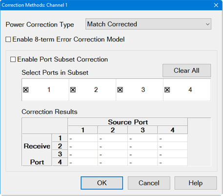
Power Wave Correction TypeMatch Corrected - These waves are calculated from the actual waves and the S-parameters of the DUT to determine the waves if the VNA test ports were perfectly matched. However, you may not want match correction in the following cases:
Actual Waves - These are the full error corrected actual waves at device reference planes. Response Corrected - These are raw measurements scaled with the response terms and do not include any match correction. Selected Ports Will Correct Power Using Actual Waves (Spectrum Analyzer applications only) -
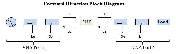
8-term Error Correction ModelEnable 8-term Error Correction Model - Check to enable the 8-term error correction model for measurement calibration. Note: In trigger hold mode, acquired data may be inaccurate after transitioning from 10 to 8 term model. In this case, it is recommended to trigger a new sweep. The reverse transition (8 to 10 term model) is safe and does not require the new sweep. The VNA may correct S-Parameters by using either the 12-term or the 8-term error correction model. (The 12-term model is also known as the 10-Term model if the two crosstalk terms are ignored.) Changing the model will affect the S-Parameter and wave measurements. When measuring a DUT, the VNA will stimulate the DUT in the forward and reverse direction, measure the waves, then calculate the S-Parameters of the DUT. A 2-port VNA forward flow diagram is shown below and will be used to compare the two correction models.
For an 8-term model, the forward direction state will measure the waves (a0, b0, a3, b3) and will calculate the corrected waves (a1, b1, a2, b2) at the DUT test ports. For a 12-term model, the VNA will measure the waves (a0, b0, b3) and will calculate the corrected waves (a1, b1, a2, b2) at the DUT test ports. The 12-term model does not need to measure the a3 wave because its value is calculated from the b3 wave and the Port 2 load match characterized during calibration. The following table describes the tradeoffs between the 8-term and 12-term models:
The VNA uses the 12-term model by default because it is fast, low noise, and typically the VNA load match is very stable. However, there are several cases where the 8-term model is a good choice:
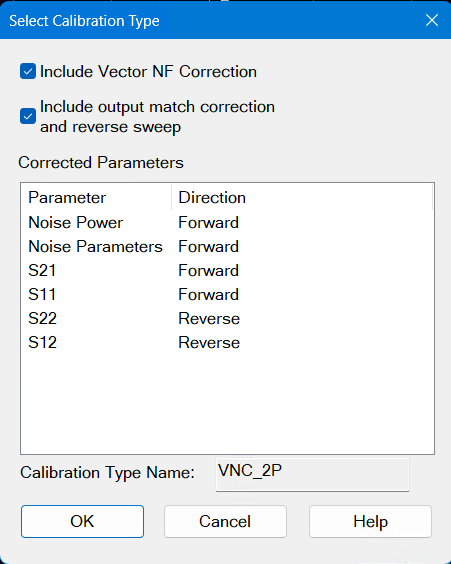
Port subset correctionEnable Port Subset Correction - Enabling port subset correction to reduce the number of corrected ports. Select Ports in Subset - Selects which ports should be included in a full N-port correction. Un-selected ports will be corrected on a “best effort” basis: In other words, these ports will be corrected with an enhanced response calibration if the error terms are available in the calset. Clear All button - De-selects all ports from correction. The button will change to Select All to include all ports for correction. To learn more about Port subset correction, go to Port Subset Correction (Devolve Calibration). Correction ResultsCorrection results are displayed in this table. This is the same table displayed when the user right-clicks on the Cal pane of the status bar at the bottom of the screen. The following indicate the correction applied: F1 - 1-port calibration. eR - Enhanced response. Blank - No correction applied. F - Multiport calibration. Select Calibration Type DialogFor Noise Figure measurements only. This dialog is found by pressing Cal and then Correction Methods (on active noise channel with calset applied).
If "Include output match correction and reverse sweep" is unselected, the S-parameter correction will be Enhanced Response. If "Include Vector NF Correction" is unselected, Scalar noise correction will be performed. If the vector correction calibration was not performed, this checkbox will be grayed out. If scalar correction calibration was not performed (S-paramter only), both checkboxes will be greyed out, and only a full 2-port S-parameter correction is performed. The Calibration Type Name is displayed in the bottom for reference. This name can be used with the SCPI command CALC:MEAS:CORR:TYPE. |
||||||||||