How Do I Make a Dynamic Power Analysis Measurement?
Last updated: January 15, 2009
The dynamic power analysis measurement is a flexible tool that allows you to measure the output power of your UE versus time. This section provides examples for two main uses of the measurement, UE power calibration and HS-DPCCH power versus time measurement.
UE Power Calibration
This procedure assumes that the test set is in
Active Cell Operating Mode
. However, this measurement is also available in
and
FDD Test Operating Mode
CW Operating Mode
.
- Set the test set's receiver to the proper power and frequency for your UE's power sequence:
- Press the Measurement selection key.
-
Select the
Dynamic Power Analysismeasurement. -
Select
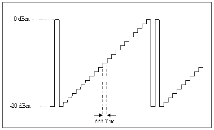
Dynamic Power Setup( F1 ) and set the measurement parameters as needed. For example, to analyze the power sequence shown below, set the parameters as follows:
-
Set
Stepsto23. -
Set
Step Lengthto666.7 us. -
Set
RF Rise Trigger Thresholdto-10 dBm. -
Set
Trigger Qualification StatetoOn. -
Set
Trigger Qualification TypetoRF Rise and Fall. -
Set
Trigger Qualification Rise Thresholdto10 dB. -
Set
Trigger Qualification Fall Thresholdto10 dB. -
Set
Trigger ArmtoSingle. -
Set
Trigger SourcetoRF Rise.
-
Set
-
Select
Close Menu( F6 ). - Place your UE into a test mode which will force it to continuously transmit the power sequence you desire to test. (To ensure that the measurement executes as quickly as possible, the UE should transmit its power sequence continuously until the measurement completes. This ensures that as soon as the measurement is done auto-ranging, another power sequence is immediately available for measurement. See Auto-ranging in the Dynamic Power Analysis Measurement for UE Power Calibration .)
-
If
Trigger Armis set toSingle, you must press the START SINGLE key to begin the measurement. -
Select
Axis Control( F2 ). Set the axis control parameters as needed. SelectReturn( F6 ). -
Select
Marker( F3 ) to turn on the marker on the graphical display.
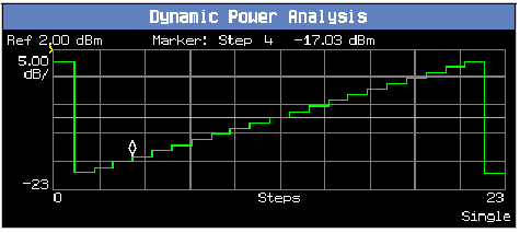
A typical result is shown below:

Measuring 3GPP TS 34.121 v7.5.0 s5.7A HS-DPCCH
This section is only applicable to the lab application or a test application with the required feature license.
Overview:
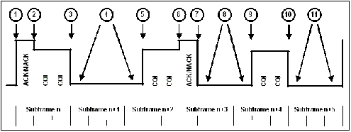
3GPP TS 34.121 s5.7A defines a specific UE output power waveform:

It then specifies the required relative power changes for the test points numbered above. The test is performed with the UE's DPCCH+DPDCH power equal to 0 dBm and also at maximum output power (the resulting power pattern and test points are altered somewhat at maximum power, but the ACK/CQI sequence is unchanged).
Procedure:
-
Set parameters that can only be set in cell off operating mode (and other parameters that are set from the same menu):
-
Set
Operating Mode( F1 ) toCell Off. -
Select
34.121 Preset Call Configurations( F11 onCall Parms 1 of 3) and select5.2C, 5.7A, 5.13.1A, 5.13.1AA, 5.13.2A with QPSK. You may then skip any steps marked with [34.121 Call Config] in this procedure. -
Select
Channel (UARFCN) Parms( F12 onCall Parms 1 of 3). SetDL Channel( F7 ) andUplink Channel( F8 ) to the appropriate "mid range" frequencies for your UE's operating band, as specified by 3GPP TS 34.108 5.1.1 (for example, for operating band II, setDL Channel=9800). -
[34.121 Call Config]
Select
Uplink Parameters( F4 onCall Control 2 of 5).-
[34.121 Call Config]
Set
Uplink DPCH Bc/Bd ControltoManual. -
[34.121 Call Config]
Set
Manual Uplink DPCH Bcto15(for 34.121 v7.5.0 Table C.10.1.4 sub-test 3). -
[34.121 Call Config]
Set
Manual Uplink DPCH Bdto8(for 34.121 v7.5.0 Table C.10.1.4 sub-test 3). -
[34.121 Call Config]
Set
Maximum Uplink Transmit Power Levelto+21 dBm.
-
[34.121 Call Config]
Set
-
Set
Operating ModetoActive Cell(pressing the CALL SETUP key quickly brings you back to the top levelCall Controlmenu).
-
Set
-
[34.121 Call Config]
Set
Channel Type( F8 ) to12.2k RMC + HSDPA. -
Select
HSDPA Parameters(HSPA Parameters( F10 ), F10 ).-
Select
HSDPA RB Test Mode Setup( F8 ).-
[34.121 Call Config]
Set
HS-DSCH Configuration TypetoFRC(this is the default value). -
[34.121 Call Config]
Set
FRC TypetoH-Set 1 QPSK(this is the default value). -
Set
CN Domainas needed (by default it is set toPS Domain). Note, before you can establish a connection in the PS domain, the UE must attach to the test set. To enable this, thePS Domain Informationparameter (underCell Parameters, F12 onCall Control 2 of 5) must be set toPresentwhen the UE registers (attaches) with the test set.
-
[34.121 Call Config]
Set
-
[34.121 Call Config]
Select
HSDPA Uplink Parameters( F11 ).-
[34.121 Call Config]
Set
DeltaACKandDeltaNACKto8. -
[34.121 Call Config]
Set
DeltaCQIto7. -
[34.121 Call Config]
Set
Ack-Nack Repetition Factorto1(this is the default value). -
[34.121 Call Config]
Set
CQI Feedback Cycle (k)to4 ms. -
[34.121 Call Config]
Set
CQI Repetition Factorto1(this is the default value).
-
[34.121 Call Config]
Set
-
Select
-
Test Application: Select
Cell Parameters( F2 ).
Lab Application: SelectCell Info( F2 ), thenCell Parameters( F2 ).
( from theCall Control 2 of 5menu)-
[34.121 Call Config]
Set
Default DPCH Offset (DOFF)to3 x 512 chips. -
Set
PS Domain InformationtoPresent(this is the default value in the lab application) if you plan to establish the HSDPA connection in the PS domain (i.e. if you've setCN DomaintoPS DomainorCS/PS Domainin step 3 above). -
Qqualmin and Qrxlevmin are fixed to -24 dB and -115 dBm, respectively, in the test application. In the lab application these are the default values for these parameters. They are accessible from
Cell Info,Reselection Parameters( F3 ).
-
[34.121 Call Config]
Set
-
[34.121 Call Config]
Select
Generator Info( F3 onCall Control 2 of 5), selectConnected DL Channel Levels( F4 ), then selectHSDPA Conn DL Channel Levels( F4 ).-
[34.121 Call Config]
Set
Cell 1 Connected HSDPA CPICH Levelto-10 dB(this is the default value). -
[34.121 Call Config]
Set
Cell 1 Connected HSDPA P-CCPCH/SCH Levelto-12 dB(this is the default value). -
[34.121 Call Config]
Set
Cell 1 Connected HSDPA PICH Levelto-15 dB(this is the default value). -
[34.121 Call Config]
Set
Cell 1 Connected HSDPA DPCH Levelto-9 dB. -
[34.121 Call Config]
Set
Cell 1 Sum of Active Conn HS-PDSCH Levelsto-3 dB(this is the default value). -
[34.121 Call Config]
Set
Cell 1 Connected HS-SCCH 1 Levelto-8 dB.
-
[34.121 Call Config]
Set
-
[34.121 Call Config]
Select
RB Test Mode Setup( F6 onCall Control 3 of 5) and setUE Loopback TypetoType 1(this is the default value). - Set any other parameters needed to establish a connection with your UE, then power on the UE and wait for it to register (attach). See Establishing an HSDPA Connection .
-
Select
Originate Call( F3 onCall Control 1 of 5). -
Set
Cell Power( F7 onCall Parms 1 of 3) to-86 dBm/3.84 MHz. -
Select
UL CL Power Ctrl Parameters( F8 onCall Parms 3 of 3). -
To perform the test such that the DPCCH+DPDCH power is equal to 0 dBm, set
UE Target Power( F7 onCall Parms 3 of 3) to0 dBm. The test set drives the UE's power to the specified value, while also appropriately ranging the test set's measurement receiver. -
Select
UL CL Power Ctrl Parameters( F8 onCall Parms 3 of 3). SetUL CL Power Ctrl ModetoAlternating bits. - Press the Measurement selection key.
-
Select
Dynamic Power Analysis. -
Set up the measurement:
-
Select
Dynamic Power Setup( F1 ). -
Select
34.121 5.7A Measurement Configuration, then selectYes. You may then skip any steps marked with [34.121 Meas Config] . -
[34.121 Meas Config]
Set
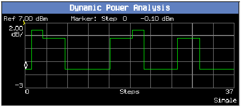
Stepsto37. -
[34.121 Meas Config]
Set
Step Lengthto333.3 us. -
[34.121 Meas Config]
Set
Measurement Intervalto283.3 us(to exclude the transient periods). -
[34.121 Meas Config]
Set
RRC FiltertoOff(to measure "mean power"). -
[34.121 Meas Config]
Set
Trigger ArmtoSingle, if desired. -
[34.121 Meas Config]
Set
Trigger SourcetoHS-DPCCH. -
[34.121 Meas Config]
Set
Trigger Delayto-308.3 us.(To trigger the measurement on the half slot just prior to subframe 0, a trigger delay of -333.3 us is required. To exclude the transient period after the slot boundary, a trigger delay of -333.3 us + 25 us = -308.3 us is required.) -
[34.121 Meas Config]
Set
HS-DPCCH Trigger Subframe Alignmenttosubframe 0(this is the default value). -
Select
Close Menu( F6 ).
-
Select
-
If you set
Trigger ArmtoSingle, press the START SINGLE key to begin the measurement. -
Adjust the
Axis Control( F2 ) as needed and use theMarker( F3 ) to measure the power changes for each of the specified steps.
-
To perform the test at the UE's maximum output power:
-
Select
UL CL Power Ctrl Parameters( F8 onCall Parms 3 of 3). SetUL CL Power Ctrl ModetoActive bits. -
Set
UE Target Power( F7 onCall Parms 3 of 3) to a high value, such as24 dBm. The test set drives the UE to the specified level (or simply continues to send all up bits if the UE does not reach that level), while also appropriately ranging the test set's measurement receiver. -
Select
UL CL Power Ctrl Parameters( F8 ). SetUL CL Power Ctrl ModetoAll Up bits. - Repeat steps 16 and 17.
-
Select
Related Topics
Dynamic Power Analysis Measurement Description